

It is important to know the different types of transformers for electrical engineering applications and to design power systems. Transformers are electromagnetic devices based on the principles of electromagnetic induction discovered by Michael Faraday, and they perform very important functions for power generation, transmission, distribution, and electronic circuits. This large reference material on transformers covers various types of transformers distinguished by the voltage level, core material, winding arrangement, and application for specific purposes, giving people using transformers theoretical knowledge and implementation practice taken by electrical engineers around the world. We have covered Transformer construction and operation in detail in the previous tutorial. Here we will cover different types of transformers used in different types of applications. However, all types of transformers follow the same principles, but they have different construction methods. And with a little bit of effort, you can also build your own transformer, but while building the transformer, one should always follow transformer protection techniques.
Quick Overview
Duration: 2-3 hours | Type: Power Electronics | Difficulty: Intermediate
Technical Scope:
Transformer types, voltage transformation
Use Cases:
Power distribution, electronics design
Table of Contents
- What are the 3 Main Types of Transformers?
- What are the Two Main Classes of Transformers?
- What are the 4 Types of Transformers?
- 1. Step-Down Transformer
- 2. Step-Up Transformer
- └ Real-World Application Example
- 3. Isolation Transformer
- Technical Comparison: Main Transformer Types
- Transformer Types Based on Core Material
- 1. Iron Core Transformer
- 2. Ferrite Core Transformer
- 3. Toroidal Core Transformer
- 4. Air Core Transformer
- Types of Transformers Based on Winding Arrangement
- Auto-Winding Transformer Types and Applications
- Types of Transformers Based on Usage and Applications
- 1. Power Domain Transformer Types
- └ (a) Power Transformer
- └ (b) Measurement Transformer
- └ (c) Distribution Transformer
- 2. The Transformer used in the Electronics Domain
- └ (a) Pulse Transformer
- └ (b) Audio Output Transformer
- └ (C) Current Transformer
- └ (D) Voltage Transformer
- └ (E) RF Transformers
- Additional Types of Transformers and Their Applications
- └ 1. Variable Auto Transformer (Variac)
- └ 2. Instrument Transformers
- └ 3. Resonant Transformers
- └ 4. Matching Transformers
- └ 5. Toroidal Transformers
- └ 6. Three-Phase Transformers
- └ 7. Rectifier Transformers
- Technical References and Industry Standards
- Frequently Asked Questions: Types of Transformers
- Broaden Your Transformer Expertise
What are the 3 Main Types of Transformers?
The three main types of transformers based on voltage transformation are:
- Step-Up Transformer - Increases voltage from primary to secondary winding
- Step-Down Transformer - Decreases voltage from primary to secondary winding
- Isolation Transformer - Maintains the same voltage while providing electrical isolation
These three types of transformers form the foundation of all transformer applications in the electrical and electronics domains.
What are the Two Main Classes of Transformers?
Transformers can be broadly classified into two main classes:
- Power Transformers - Used in transmission and distribution systems (ratings above 25 MVA)
- Distribution Transformers - Used for final voltage reduction to consumers (ratings below 25 MVA)
This classification helps distinguish between transmission-level transformers and consumer-level transformers in power systems.
What are the 4 Types of Transformers?

A Transformer can have multiple types of construction. The transformer does not have any electrical connection from one side to another; still, the two electrically independent coils can conduct electricity by electromagnetic flux. A transformer can have multiple coils or windings on the primary side as well as on the secondary side. In several cases, multiple primary sides, where two coils are connected in series, are often called a center tapped. This center-tapped condition can also be seen on the secondary side.
Transformers can be constructed in a way that it can convert the voltage level of the primary side to the secondary side. Depending on the voltage level, there are three main types of transformers, namely Step Down, Step Up and Isolation Transformer. These voltage-based transformer types are fundamental to all electrical applications.
1. Step-Down Transformer

A step-down Transformer is used in both Electronics and Electrical domains. A step-down transformer converts the primary voltage level to a lower voltage across the secondary output. This is achieved by the ratio of primary and secondary windings. For step-down transformers, the number of windings is higher across the primary side than the secondary side. Therefore, the overall winding ratio of primary and secondary always remains more than 1.
In electronics, many applications run on 5V, 6V, 9V, 12V, 24V or in some cases 48V. To convert the single-phase power outlet voltage of 230V AC to the desired low voltage level, Step-down transformers are required. In instrumentation as well as in many electrical types of equipment, a Step-Down transformer is the primary requirement for the Power section. They are also used in power adapters and cell phone charger circuits.
In electrical, step-down transformers are used in electrical distribution system which works on very high voltage to ensure low loss and cost-effective solutions for long-distance power delivery requirements. To convert the high voltage to a low voltage supply line, a step-down transformer is used.
For more details on step-down transformer calculations and design, check our transformer basics tutorial. These voltage reduction transformer types are also commonly used in power supply circuits.
2. Step-Up Transformer

The step-up transformer is exactly the opposite of the step-down transformer. The step-up transformer increases the low primary voltage to a high secondary voltage. Again, it is achieved by the ratio of the primary and secondary winding ratios. For the Step-Up transformer, the ratio of the primary winding and the Secondary winding remains less than 1. That means the number of turns in the secondary winding is higher than in the primary winding.
In electronics, step-up transformers are often used in stabilisers, inverters, etc, where low voltage is converted to a much higher voltage.
A step-up transformer is also used in Electrical power distribution. High voltage is required for power distribution-related applications. A step-up transformer is used in the grid to step up the voltage level before the distribution.
Real-World Application Example
In industrial settings, a typical 480V to 120V step-down transformer is commonly used in control panels. For instance, a 10 KVA step-down transformer can safely power multiple 120V control circuits while maintaining isolation from the high-voltage primary system. Always ensure proper grounding and overcurrent protection according to NEC Article 450.
3. Isolation Transformer

The isolation transformer does not convert any voltage levels. The Primary voltage and the secondary voltage of an isolation transformer always remain the same. This is because the primary and the secondary winding ratios are always equal to 1. That means the number of turns in the primary and secondary windings is the same in the isolation transformer.
The isolation transformer is used to isolate the primary and secondary. As discussed previously, the transformer does not have any electrical connections between primary and secondary; it is also used as an isolation barrier where the conduction happens only with the magnetic flux. It is used for safety purposes and to cancel noise transfer from primary to secondary or vice versa.
Technical Comparison: Main Transformer Types
| Transformer Type | Voltage Ratio | Typical Applications | Efficiency Range | Power Rating |
|---|---|---|---|---|
| Step-Down | > 1:1 | Power supplies, distribution | 95-99% | 1VA to 500MVA |
| Step-Up | < 1:1 | Power transmission, inverters | 95-99% | 10MVA to 1000MVA |
| Isolation | 1:1 | Medical equipment, safety | 92-98% | 100VA to 25MVA |
| Auto | Variable | Voltage regulation, testing | 98-99.5% | 1KVA to 100MVA |
Transformer Types Based on Core Material

The transformer transfers the energy by conducting electromagnetic flux through a core material. Different core materials produce different flux densities. Depending on the core materials, several types of transformers are used in the power and electronics domain.
1. Iron Core Transformer
The iron core transformer uses multiple soft iron plates as the core material. Due to the excellent magnetic properties of iron, the flux linkage of the iron core transformer is very high. Thus, the efficiency of the iron core transformer is also high.

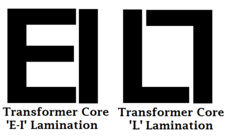
The soft iron core plates can be available in multiple shapes and sizes. The coils of the primary and secondary are wound or wrapped on a coil former. After that, the coil former is mounted in soft iron core plates. Depending on the core size and shape, a different type of core plate is available on the market. A few common shapes are E, I, U, L, etc. The iron plates are thin, and multiple plates are bunched together to form the actual core. For example, E-type cores are made with thin plates with the look of the letter E.
Iron core transformers are widely used and usually heavier in weight and shape.
2. Ferrite Core Transformer
A ferrite core transformer uses a ferrite core due to its high magnetic permeability. This type of transformer offers very low losses in high-frequency applications. Due to this, ferrite core transformers are used in high-frequency applications such as switch-mode power supply (SMPS), RF-related applications, etc.

Ferrite core transformers are available in different shapes and sizes depending on the application requirement. It is mainly used in electronics rather than electrical applications. The most common shape in the ferrite core transformer is the E core.
3. Toroidal Core Transformer

The toroidal core transformer uses toroid-shaped core material, such as an iron core or ferrite core. Toroids are ring or doughnut-shaped core materials and are widely used for superior electrical performance. Due to the ring shape, the leakage inductance is very low and offers very high inductance and Q factors. The windings are relatively short, and their weight is much less than traditional, same-rating transformers.
4. Air Core Transformer
The Air Core transformer does not use any physical magnetic core as the core material. The flux linkage of the air-core transformer is made entirely using the air.

In an air core transformer, the primary coil is supplied with alternating current, which produces an electromagnetic field around it. When a secondary coil is placed inside the magnetic field, as per the Faraday law of induction, the secondary coil is induced with a magnetic field, which is further used to power the load.
However, an air core transformer produces low mutual inductance compared to a physical core material such as iron or ferrite core.
It is used in portable electronics as well as radiofrequency-related applications. Due to the absence of physical core material, it is very light in terms of weight. Properly tuned air-core transformers are also used in wireless charging solutions, where the primary windings are constructed inside the charger and the secondary windings are situated inside the targeted device.
Types of Transformers Based on Winding Arrangement

The transformer can be classified using winding orders. One of the popular types is Auto-Winding Transformers.
Auto-Winding Transformer Types and Applications
Till now, the primary and secondary winding is fixed, but in the case of an auto-winding transformer, the primary and secondary coils can be connected in series, and the centre-tapped node is movable. Depending on the centre-tapped position, the secondary voltage can be varied.

The auto is not the short form of Automatic; rather, it is to notify the self or single coil. This coil forms a ratio which consists of two parts, primary and secondary. The position of the center tap node determines the primary and secondary ratios, thus varying the output voltage.

The most common use is the VARIAC, an instrument to produce variable AC from a steady AC input. It is also used in Power transmission and distribution-related applications where the high-voltage lines need to be changed frequently.

You can also find them with multiple tapping's instead of any moving parts. From these types of transformers, you can get different voltages by using different voltage tapping's. This type of transformer is commonly used in voltage stabilisers, UPS and inverters, and the different tapping's are selected using power relays.
Types of Transformers Based on Usage and Applications
There are several specialised types of transformers available that work in specific domains. These application-specific transformer types serve unique purposes in power and electronics systems. So, the transformers can be classified as below based on usage:
1. Power Domain
- Power Transformer
- Measurement Transformer
- Distribution Transformer
2. Electronics Domain
- Pulse Transformer
- Audio Output Transformer
- Current Transformer
- Voltage transformers
- RF transformers
1. Power Domain Transformer Types

In Electrical, the Power domain deals with power generation, measurement, and distribution. However, it is a very large field where transformers are an essential part of accommodating safe power conversion and successful power delivery to the substation and the end users.
The transformers which are used in the power domain can be both outdoor and indoor, but mostly outdoor.
(a) Power Transformer
Power Transformers are larger in size and used to transfer the energy to the substation or the public electricity supply. This transformer acts as a bridge between the power generator and the primary distribution grid. Depending on the Power rating and specification, Power transformers can further be classified into three categories: small power transformers, Medium Power transformers, and large power transformers. The rating can be more than 30KVA to 500-700KVA, or in some cases, can be equal to or more than 7000KVA for a small, rated power transformer. The medium-rated power transformer can be up to 50-100 MVA, whereas large power transformers are capable of handling more than 100MVA.

Due to the very high power generation, the construction of a power transformer is also critical. The construction includes solid insulating peripherals and a well-balanced cooling system. The most common power transformers are filled with oil.
The main principle of the power transformer is to convert the Low voltage, high current to a high voltage, low current. This is required to minimise the power loss in the power distribution system.
Another important parameter for the Power transformer is the phase availability. Typically, Power transformers work in three-phase systems, but in some cases, Single-phase small power transformers are also used. Three-phase power transformers are more costly and efficient than single-phase power transformers.
Understanding different power transformer types is crucial for electrical engineers working on grid systems. These high-voltage transformer types require special protection circuits for safe operation.
(b) Measurement Transformer
A measurement transformer is often referred to as an instrument transformer. This is another commonly used measurement instrument in the power domain. A measurement transformer is used to isolate the main power and convert the current and voltage in a smaller ratio to its secondary output. By measuring the output, the Phase, Current and Voltage of the actual power line can be measured.

The above image shows the construction of the current transformer.
(c) Distribution Transformer
This is used in the last phase of the power distribution system. Distribution transformers are step-down transformer, which converts High grid voltage to the end customer's required voltage, 110V or 230V. It can also be a single phase or three phases.

Distribution transformers can be smaller in shape as well as bigger, depending on the conversion capacity or ratings.
Distribution transformers can be further categorised based on the type of insulation they use. It can be a dry type or can be liquid-immersed. It is made using laminated steel plates, mostly constructed in C shape as a core material.
Distribution transformer also has a different type of classification based on the location it is used. The transformer can be mounted on a utility pole; if so, it is called a pole-mounted distribution transformer. It can be placed inside of an underground chamber, mounted on a concrete pad (pad-mounted distribution transformer) or inside an enclosed steel box.
Generally, distribution transformers have a rating of less than 200kVA.
2. The Transformer used in the Electronics Domain

In electronics, various small miniature transformers are used, which can be PCB mounted or can be fixed inside the small product enclosure.
(a) Pulse Transformer
Pulse transformers are one of the most used PCB-mounted transformers that produce electrical pulses in a constant amplitude. It is used in various digital circuits where pulse generation is needed in an isolated environment. Therefore, the pulse transformers isolate the primary and secondary and distribute primary pulses to the secondary circuit, often digital logic gates or drivers.

Properly constructed pulse transformers should require proper galvanic isolation as well as small leakage and stray capacitance.
(b) Audio Output Transformer
An Audio Transformer is another commonly used transformer in the electronics domain. It is specially used in audio-related applications where impedance matching is required. An audio transformer balances the amplifier circuit and loads, typically a loudspeaker. The audio transformer can have multiple primary and secondary coils, separated or center tapped.

So, we have covered various kinds of transformers; other than that, there are some other special-purpose transformers, but they are out of the scope of this article.
(C) Current Transformer
Just like in the power domain, we also have measurement or instrumentation transformers in the electronic domain. One of them is the current transformer, also known as CT. As the name suggests, the current transformers are used to measure AC current. Typically, the current transformers will only have one or very few turns in the primary winding. This primary winding can be of either a single turn, a coil of heavy-duty wire wrapped around the core or just a conductor or bus bar placed through a central hole. Most of the time, the CT will only have a secondary winding on a core material, and the power line wire going through the hole of the core will act as the primary winding. There are also many types of current transformers, namely the toroidal current transformer, wound current transformer and bar current transformers, to name a few. The most commonly used CT is the toroidal core transformer shown below.
Current transformer types vary based on construction - toroidal CTs, wound CTs, and bar-type CTs each serve different measurement applications in power systems.

(D) Voltage Transformer
As the name suggests, the voltage transformers are used to measure the AC voltage. These are basically just a step-down transformer, with very little output current capabilities. They will step down the voltage to a level which can be measured using microcontrollers or such. They are available in many different form factors. The most popular voltage transformer among the DIY community is the ZMPT101B.

(E) RF Transformers
The RF transformers are typically used in radio and communication equipment. They are used for their ability to transfer electrical energy between circuits while maintaining impedance matching, isolation, and signal integrity at high frequencies. The RF transformers are normally designed to operate over specific frequency ranges and to minimise loss and distortion. They are typically manufactured using specialised core materials like ferrite or powdered iron.

Additional Types of Transformers and Their Applications
There are a few more types of transformers which does not fit into any of the above categories. So let's discuss them one by one below
1. Variable Auto Transformer (Variac)
A Variac is an autotransformer with a single continuous winding and a movable contact for varying the output voltage. Adjusting the contact changes the winding portion in the circuit, providing smooth voltage adjustment from zero to above the input voltage. It is commonly used in laboratories, dimming lights, motor speed control, and equipment testing.
2. Instrument Transformers
Instrument Transformers are used to measure high voltages and currents safely, by isolating instruments from high voltage lines. Current Transformers (CTs) step down current for measurement, while Potential Transformers (PTs) step down voltage for accurate readings. We have already discussed CT and PT separately.
3. Resonant Transformers
The Resonant Transformers are designed to operate at resonant frequencies, these transformers use inductance and capacitance to maximise energy transfer. They are a special type of transformer and are common in radio transmitters, receivers, and high-frequency power supplies.
4. Matching Transformers
As the name suggests, matching transformers match the source impedance and load impedance to ensure maximum power transformer. They are widely used in audio systems to match amplifiers to speakers and in RF circuits to match antennas to transmission lines.
5. Toroidal Transformers
With a ring-shaped core, toroidal transformers offer low leakage inductance, minimal magnetic emissions, high efficiency, and compact size. They are used in applications requiring efficient power transfer.
6. Three-Phase Transformers
These transformers step up or down three-phase power for electrical transmission and distribution. Common configurations include Delta-Wye and Wye-Delta. They are essential in power generation, transmission, and industrial applications.
7. Rectifier Transformers
Specially designed for rectifier circuits, these handle high peak currents and may have multiple secondary windings. They are used in electronic power supplies and industrial DC applications.
With this, let's wrap up the article. Hope you enjoyed reading it and learnt something useful.
This comprehensive guide covers all major types of transformers used in electrical and electronics applications. From basic voltage transformation types like step-up and step-down to specialised transformer varieties like current transformers and RF transformers, each type serves specific engineering needs. Understanding these different transformer types is essential for proper selection in power systems, electronics design, and industrial applications. Whether you're working with power domain transformers for electrical distribution or electronics domain transformers for circuit applications, this classification helps engineers choose the right transformer for their specific requirements.
Technical References and Industry Standards
This guide references established electrical engineering principles and industry standards, including:
- IEEE Standard C57.12.00 - General Requirements for Liquid-Immersed Distribution, Power, and Regulating Transformers
- IEC 60076-1 - Power Transformers - General Requirements
- NEMA Standards Publication No. ST 20 - Dry-Type Transformers for General Applications
- National Electrical Code (NEC) Article 450 - Transformers and Transformer Vaults
Frequently Asked Questions: Types of Transformers
1. What are the types of transformers?
Answer: There are multiple types of transformers depending on classification criteria. Based on voltage level: 3 types (step-up, step-down, isolation). Based on core material: 4 main types (iron core, ferrite core, toroidal, air core). Based on usage: dozens of specialised types including power transformers, current transformers, voltage transformers, and RF transformers.
2. What are the 4 types of transformers commonly used?
Answer: The 4 most commonly used transformer types are: Step-down transformers (voltage reduction), Step-up transformers (voltage increase), Power transformers (electrical grid applications), and Distribution transformers (final consumer voltage delivery).
3. What are the main types of transformers in electrical engineering?
Answer: In electrical engineering, the main transformer types include: Power transformers for transmission systems, Distribution transformers for consumer supply, Instrument transformers (CT and PT) for measurement, Auto transformers for voltage regulation, and Three-phase transformers for industrial applications.
4. What are the main types of transformers based on voltage level?
Answer: Based on voltage level, the primary types of transformers are Step-up transformers, which increase the voltage level from primary to secondary winding, Step-down transformers, which decrease the voltage level from primary to secondary winding and isolation transformers, which maintain the same voltage level on both the primary and secondary sides while providing electrical isolation.
5. How does a step-up transformer increase voltage?
Answer: A step-up transformer increases voltage by having more turns in the secondary winding than in the primary winding. This turns ratio directly influences the voltage transformation.
6. What are the advantages of using a toroidal transformer?
Answer: Toroidal transformers offer several advantages, including Low leakage inductance - This minimises energy loss and improves efficiency. Reduced magnetic field emissions - This makes them suitable for sensitive electronic equipment. High efficiency -Due to reduced core losses and lower leakage inductance. Compact size and weight -Compared to conventional transformers with similar power ratings.
7. What are instrument transformers used for?
Answer: Instrument transformers are essential for safely measuring high voltages and currents in power systems. Current transformers (CTs) measure high currents by passing the power line through their core and inducing a proportional current in the secondary winding. Potential transformers (PTs) measure high voltages by stepping them down to a safe level for measurement using a voltmeter.
8. What is the difference between a power transformer and a distribution transformer?
Answer: Power transformers are large transformers used in power generation and transmission, typically stepping up voltage to high levels for efficient long-distance transmission. They have high power ratings. Distribution transformers are smaller transformers used in the final stage of the power distribution system, stepping down high-voltage transmission lines to the lower voltages used by consumers (e.g., 120V or 240V).
9. How do matching transformers improve audio system performance?
Answer: Matching transformers improve audio system performance by maximising power transfer between the amplifier and the loudspeaker. By adjusting the impedance ratio through the turns ratio, they ensure that the amplifier's output impedance matches the loudspeaker's impedance, minimising power loss and maximising sound output.
10. What are some common applications of three-phase transformers?
Answer: Three-phase transformers are widely used in: Power generation and transmission: Stepping up voltage for efficient long-distance transmission. Industrial applications: Providing power to large industrial equipment and machinery. Commercial buildings: Supplying power to various electrical loads.
11. What are the advantages of using dry-type transformers?
Answer: Dry-type transformers offer several advantages, including: Fire safety: They are less prone to fire hazards compared to oil-filled transformers. Reduced environmental impact: They eliminate the risk of oil spills. Suitability for indoor installations: They can be installed in various locations, including indoor spaces.
12. What is the role of a rectifier transformer in a power supply?
Answer: Rectifier transformers are specifically designed to provide the necessary voltage and current for rectifier circuits, which convert AC power to DC power. They are crucial components in various electronic devices and power supplies.
Broaden Your Transformer Expertise
Master advanced transformer principles by diving into specialized topics like current transformer classifications, protection circuit strategies, and the role of dot convention in winding polarity. These in-depth tutorials will help solidify your understanding and prepare you for more complex transformer applications.

Learn about different types of current transformers (CTs) used in electrical systems for metering and protection. Learn about bar-type, cable-type, bushing-type, block-type, single-phase, three-phase, wound core, toroidal, and split-core CTs. Find out how they work and their applications in power grids, substations, and industrial setups.

All About Transformer Protection and Transformer Protection Circuits
In this article we will talk about the most common principles used to protect transformers from catastrophic failures.

Understanding Dot Convention in Transformers
The Dot convention is a type of polarity marking for transformer windings showing which end of the winding is which, in relation to the other windings.
