
Power inverters are fundamental devices for power electronics that convert DC (Direct Current) into AC (Alternating Current). There are many types of power inverters specific for use in residential, commercial, and industrial systems. It is important to understand the types of power inverters in power electronics to make the appropriate decision about the type of power inverter you would like to use for your needs.
The biggest drawback of AC power is that it can't be stored directly for future use. For this reason, AC power must first be converted to DC and then stored in batteries and ultra-capacitors.. Once you want to use AC power, power inverters will convert the stored DC back to AC to supply power to operate AC-based appliances and equipment. So, the device which converts DC into AC is called an Inverter.
Table of Contents
- Different Types of Power Inverters
- (I)What are the 3 Types of Inverters Based on Output Waveform
- (II) Power Inverter Types Based on Input Source
- └ Current Source vs Voltage Source Inverters
- (III) Types of Inverters in Power Electronics for Different Loads
- (IV) Inverter Types Based on PWM Control Methods
- (V) Multi-level vs Two-level Inverter Types
- Summary: Choosing the Right Power Inverter Type
- Deepen Your Power Electronics Knowledge
Different Types of Power Inverters - Complete Classification
Inverters can be classified into many types based on output, source, type of load, etc. Below is the complete classification of the inverter circuits:
(I) According to the Output Characteristic
- Square Wave Inverter
- Sine Wave Inverter
- Modified Sine Wave Inverter
(II) According to the Source of Inverter
- Current Source Inverter
- Voltage Source Inverter
(III) According to the Type of Load
- Single Phase Inverter
- Half Bridge Inverter
- Full Bridge Inverter
- Three-Phase Inverter
- 180-degree mode
- 120-degree mode
(IV) According to different PWM Techniques
- Simple Pulse Width Modulation (SPWM)
- Multiple Pulse Width Modulation (MPWM)
- Sinusoidal Pulse Width Modulation (SPWM)
- Modified sinusoidal Pulse Width Modulation (MSPWM)
(V) According to the Number of Output Level
- Regular Two-Level Inverter
- Multi-Level Inverter
Now we will discuss all of them one by one. You can check a sample 12V DC to 220V AC Inverter Circuit design here.
(I)What are the 3 Types of Inverters Based on Output Waveform
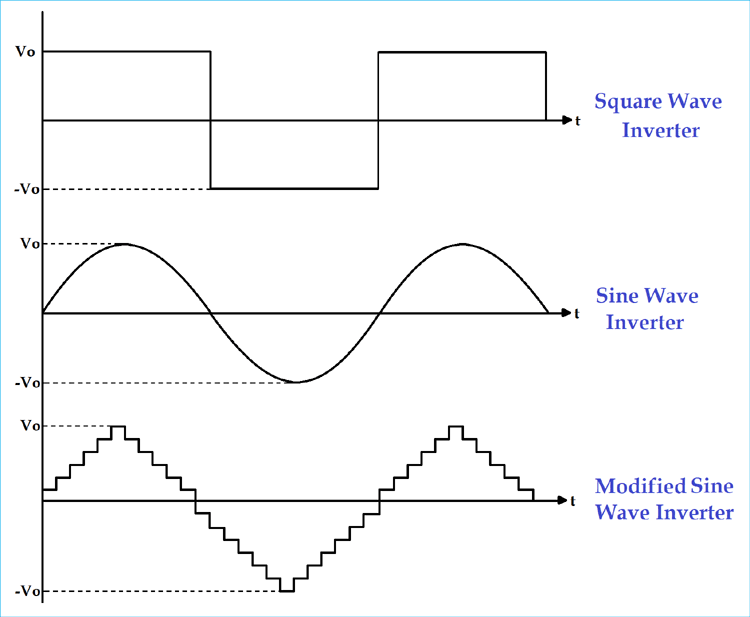
According to the output characteristic of an inverter, there can be three different types of inverters.
- Square Wave Inverter - Produces a square waveform output, the least expensive, but limited to applications
- Modified Sine Wave Inverter - Produces a stepped wave form, a balance of cost and performance
- Pure Sine Wave Inverter - produces a clean sine wave, highest quality and most expensive
These power inverter types differ in their output quality, cost, and suitable applications. Pure sine wave inverters are preferred for sensitive electronics, while square wave inverters are suitable for simple resistive loads. we have done many others projects based on Pure Sine Wave Inverter like Pure Sine Wave Inverter Using Arduino,300W Pure Sine Wave Inverter.
1) Square Wave Inverter - Basic Power Inverter Type
The square wave inverter is the simplest type of the various inverter types. These inverters produce a square wave output voltage that is fundamentally different from the pure sine wave expected by most appliances. Square wave inverters are the cheapest option, but because their output quality is so poor under most operating conditions, their applications are limited.
Applications: Simple resistive loads, universal motors, and basic light fixtures. Note, however, that the square wave could damage sensitive electronics as a result of a square wave's harshness; thus, it is not appropriate for computers, TVs or other modern appliances.
2) Pure Sine Wave Inverter - Premium Power Inverter
Pure sine wave inverters are considered the best inverters you can buy in power electronics. They produce a clean sine wave output that is identical to grid power, so it can be used with any type of electronic equipment or appliance.
Key features: Zero harmonic distortion, use with sensitive electronics, motors run cooler/quieter. They don't interfere with audio/video equipment. Pure sine wave inverters are passive; however, they cost more than the other types of inverters, and thus are the preferred choice for residential and commercial applications.
3) Modified Sine Wave Inverter - Cost-Effective Solution
When it comes to the price vs performance ratio of inverter types, modified sine wave inverters are a good balance. Modified sine wave inverters are also referred to as stepped sine wave inverters because they produce a stepped waveform that resembles a sine wave using a series of square wave pulses.
Best applications: Most household electrical devices, power tools, and non-sensitive electronics. Although the output is not considered as clean as pure sine wave output, modified sine wave inverters can work very well for resistive loads, most motors, and basic electronic devices at a much lower cost than pure sine wave models.
(II) Power Inverter Types Based on Input Source
- Voltage Source Inverter
- Current Source Inverter
1) Current Source Inverter
In CSI, the input is a current source. This type of inverter is used in the medium voltage industrial application, where high-quality current waveforms are compulsory. But CSIs are not popular.
2) Voltage Source Inverter
In VSI, the input is a voltage source. This type of inverter is used in all applications because it is more efficient and has higher reliability, and faster dynamic response. VSI is capable of running motors without de-rating.
Current Source vs Voltage Source Inverters - Comparison
| Parameter | Voltage Source Inverter (VSI) | Current Source Inverter (CSI) |
|---|---|---|
| Input Type | Voltage Source | Current Source |
| Applications | Most commonly, all power levels | Medium voltage industrial |
| Popularity | Widely used | Limited applications |
(III) Types of Inverters in Power Electronics for Different Loads
- Single-phase Inverter
- Three-phase Inverter
1) single-phase inverter
Generally, residential and commercial load uses single-phase power. The single-phase inverter is used for this type of application. The single-phase inverter is further divided into two parts;
- Single-Phase Half-Bridge Inverter
- Single-Phase Full-Bridge Inverter
A) Single-Phase Half-Bridge Inverter
This type of inverter consists of two thyristors and two diodes, and the connection is as shown in figure below.
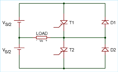
In this case, the total DC voltage is Vs and divided into two equal parts, Vs/2. Time for one cycle is T sec.
For the half cycle of 0 <t <T/2, thyristor T1 conducts. The load voltage is Vs/2 due to the upper voltage source Vs/2.
For the second half cycle of T/2 <t <T, thyristois r T1 is commutated and thyristor T2 conducts. During this period, the load voltage is -Vs/2 due to the lower source Vs/2.
Vo = Vs/2
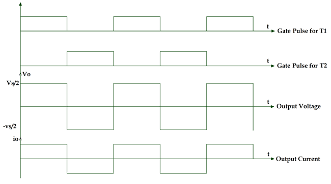
By this operation, we can get an alternating voltage waveform with 1/T Hz frequency and Vs/2 peak amplitude. The output waveform is a square wave. It will be passed through the filter and remove unwanted harmonics, which gives us a pure sine waveform. The frequency of the waveform can be controlled by the ON time (Ton) and OFF time (Toff) of the thyristor.
The magnitude of the output voltage is half of the supply voltage, and the source utilisation period is 50%. This is a disadvantage of half half-bridge inverter, and the solution to this is a full-bridge inverter.
B) Single-Phase Full-Bridge Inverter
In this type of inverter, four thyristors and four diodes are used. The circuit diagram of a single-phase full bridge is as shown in the figure below.
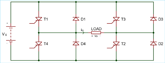
At a time, two thyristors T1 and T2 conduct for the first half cycle 0 < t < T/2. During this period, the load voltage is Vs, which is similar to the DC supply voltage.
For the second half cycle, T/2 < t < T, two thyristors, T3 and T4, conduct. The load voltage during this period is -Vs.
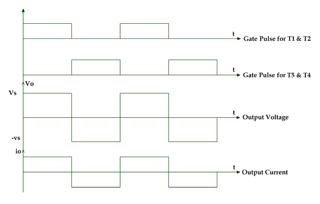
Here we can get the AC output voltage same as the DC supply voltage, and the source utilisation factor is 100%. The output voltage waveform is square, and the filters are used to convert it into a sine wave.
If all thyristors conduct at the same time or in a pair of (T1 and T3) or (T2 and T4) then the source will be short-circuited. The diodes are connected in the circuit as feedback diodes because it is used for the energy feedback to the DC source.
If we compare a full bridge inverter with a half bridge inverter, for the given DC supply voltage load, the output voltage is two times and the output power is four times in a full bridge inverter.
2) Three-Phase Bridge Inverter
In case of industrial load, a three-phase AC supply is used, and for this, we have to use a three-phase inverter. In this type of inverter, six thyristors and six diodes are used, and they are connected as shown inthe figure below.
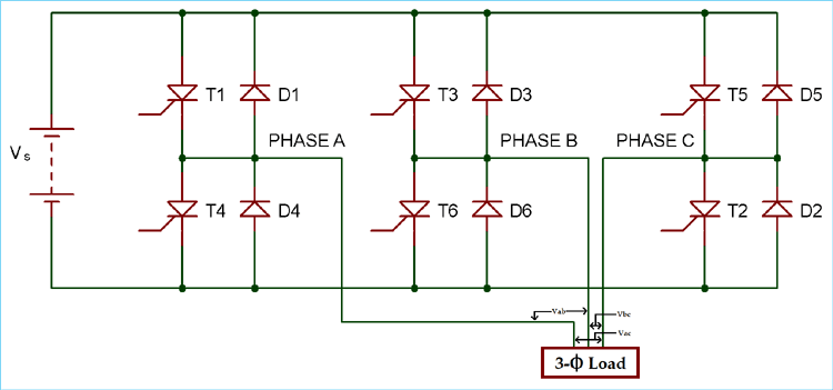
It can operate in two modes according to the degree of gate pulses.
- 180-degree mode
- 120-degree mode
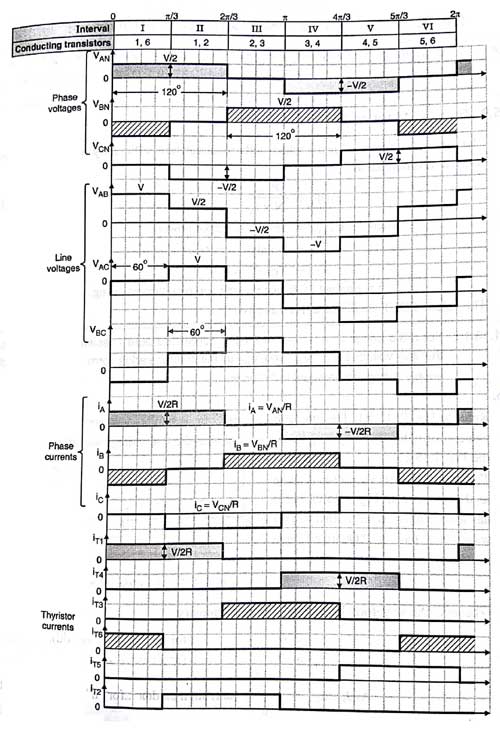
A) 180-degree mode
In this mode of operation, the conduction time for the thyristor is 180 degrees. At any time of the period, three thyristors (one thyristor from each phase) are in conduction mode. The shape of the phase voltage is three stepped waveforms, and the shape of the line voltage is a quasi-square wave, as shown in the figure.
Vab = Va0 – Vb0
Vbc = Vb0 – Vc0
Vca = Vc0 – Va0
| Phase A | T1 | T4 | T1 | T4 | |||||||||
| Phase B | T6 | T3 | T6 | T3 | T6 | ||||||||
| Phase C | T5 | T2 | T5 | T2 | T5 | ||||||||
| Degree | 60 | 120 | 180 | 240 | 300 | 360 | 60 | 120 | 180 | 240 | 300 | 360 | |
| Thyristor conducts | 1 5 6 | 6 1 2 | 1 2 3 | 2 3 4 | 3 4 5 | 4 5 6 | 1 5 6 | 6 1 2 | 1 2 3 | 2 3 4 | 3 4 5 | 4 5 6 | |
In this operation, the time gap between the commutation of the outgoing thyristor and the conduction of the incoming thyristor is zero. So, the simultaneous conduction of incoming and outgoing thyristors is possible. It results in a short circuit of the source. To avoid this difficulty, a 120-degree mode of operation is used.
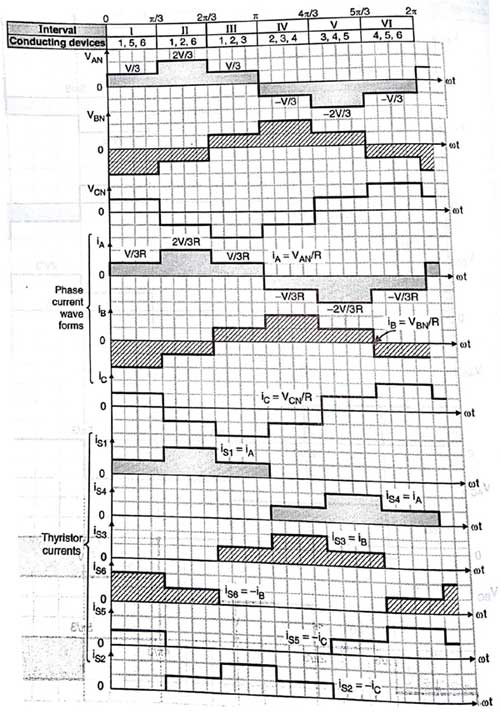
B) 120-degree mode
In this operation, at a time, only two thyristors conduct. One of the phases of the thyristor is neither connected to the positive terminal nor connected to the negative terminal. The conduction time for each thyristor is 120 degrees. The shape of the line voltage is a three-step waveform, and the shape of the phase voltage is a quasi-square waveform.
Phase A | T1 |
| T4 |
| T1 |
| T4 |
| ||||
Phase B | T6 |
| T3 |
| T6 |
| T3 |
| T6 | |||
Phase C |
| T2 |
| T5 |
| T2 |
| T5 | ||||
degree | 60 | 120 | 180 | 240 | 300 | 360 | 60 | 120 | 180 | 240 | 300 | 360 |
Thyristor conducts | 1 6 | 2 1 | 3 2 | 3 4 | 4 5 | 6 5 | 1 6 | 2 1 | 3 2 | 3 4 | 4 5 | 5 6 |
The waveform of line voltage, phase voltage and gate pulse of the thyristor is as shown in the above figure.
In any power electronic switches, there are two types of losses: conduction loss and switching loss. The conduction loss means ON state loss in the switch, and the switching loss means OFF state loss in the switch. Generally, the conduction loss is greater than the switching loss in most of the operation.
If we consider a 180-degree mode for one 60-degree operation, three switches are open and three switches are closed. Means total loss is equal to three times of conduction loss plus three times of switching loss.
Total loss in 180-degree = 3 (conductance loss) + 3 (switching loss)
If we consider a 120-degree mode for one 60-degree operation, two switches are open, and the rest of the four switches are closed. Means total loss is equal to two times of conductance loss plus four times of switching loss.
Total loss in 120-degree = 2 (conductance loss) + 4 (switching loss)
(IV) Inverter Types Based on PWM Control Methods
- Single Pulse Width modulation (single PWM)
- Multiple Pulse Width Modulation (MPWM)
- Sinusoidal Pulse Width Modulation (SPWM)
- Modified Sinusoidal Pulse Width Modulation (MSPWM)
The output of the inverter is a square wave signal, and this signal is not used for the load. Pulse width modulation (PWM) technique is used to control the AC output voltage. This control is obtained by controlling the ON and OFF periods of switches. In the PWM technique, two signals are used; one is a reference signal, and the second is a triangular carrier signal. The gate pulse for switches is generated by comparing these two signals. There are different types of PWM techniques.
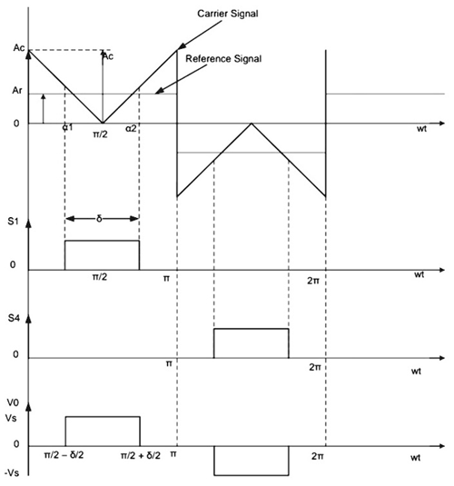
1) Single Pulse Width modulation (single PWM)
For every half cycle, the only pulse is available in this control technique. The reference signal is a square wave signal, and the carrier signal is a triangular wave signal. The gate pulse for the switches is generated by comparing the reference signal and the carrier signal. The frequency of the output voltage is controlled by the frequency of the reference signal. The amplitude of the reference signal is Ar, and the amplitude of the carrier signal is Ac; then the modulation index can be defined as Ar/Ac. The main drawback of this technique is high harmonic content.
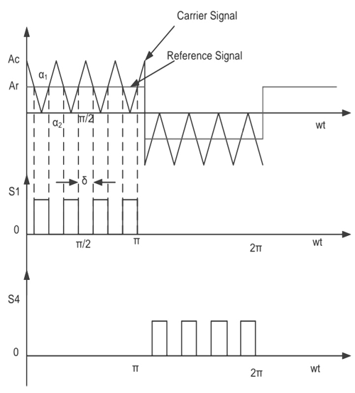
2) Multiple Pulse Width Modulation (MPWM)
The drawback of the single pulse width modulation technique is solved by multiple PWM techniques. In this technique, instead of one pulse, several pulses are used in each half cycle of the output voltage. The gate is generated by comparing the reference signal and the carrier signal. The output frequency is controlled by controlling the frequency of the carrier signal. The modulation index is used to control the output voltage.
The number of pulses per half cycle = fc/ (2*f0)
Where fc = frequency of carrier signal
f0 = frequency of the output signal
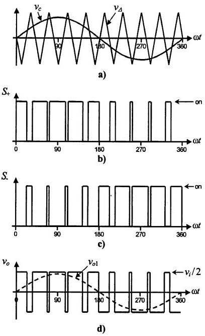
3) Sinusoidal Pulse Width Modulation (SPWM)
This control technique is widely used in industrial applications. In the above, in both methods, the reference signal is a square wave signal. But in this method, the reference signal is a sine wave signal. The gate pulse for the switches is generated by comparing the sine wave reference signal with the triangular carrier wave. The width of each pulse varies with the variation of the amplitude of the sine wave. The frequency of the output waveform is the same as the frequency of the reference signal. The output voltage is a sine wave, and the RMS voltage can be controlled by the modulation index. Waveforms are as shown in the figure below.
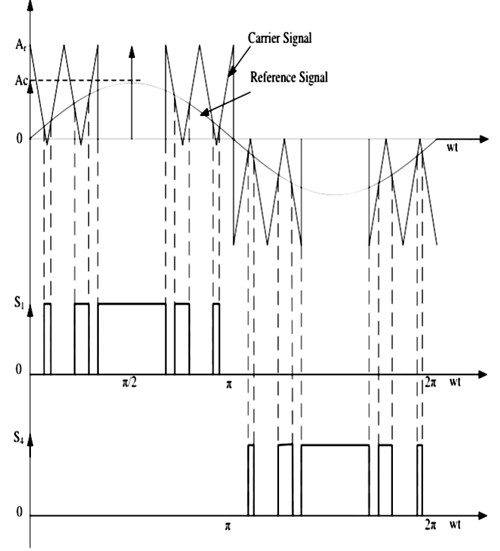
4) Modified Sinusoidal Pulse Width Modulation (MSPWM)
Due to the characteristics of the sine wave, the pulse width of the wave cannot be changed with variation in the modulation index in the SPWM technique. That is the reason, MSPWN technique is introduced. In this technique, the carrier signal is applied during the first and last 60-degree intervals of each half cycle. In this way, its harmonic characteristic is improved. The main advantage of this technique is increased fundamental component, reduced number of switching power devices and decreased switching loss. The waveform is as shown in the figure below.
(V) Multi-level vs Two-level Inverter Types
- Regular Two-Level Inverter
- Multi-level Inverter
1) Regular two-level Inverter
These inverters have only voltage levels at the output, which are positive peak voltage and negative peak voltage. Sometimes, having a zero-voltage level is also known as a two-level inverter.
2) Multilevel Inverters
These inverters can have multiple voltage levels at the output. The multi-level inverter is divided into four parts.
- Flying capacitor Inverter
- Diode-clamped Inverter
- Hybrid Inverter
- Cascade H-type Inverter
Every inverter has its design for operation. Here, we have explained these inverters briefly to get a basic idea about them.
- Modified Sine Wave Inverter
Every inverter has its design for operation. Here, we have explained these inverters briefly to get a basic idea about them.
Summary: Choosing the Right Power Inverter Type
The final decision on which of the different types of power inverters to purchase will depend You must factor in your specific application, available budget, and power quality limitations, and with this, you can use the following guide:
∗ Pure Sine Wave Inverters - for sensitive electronics
∗ Modified sine wave inverter - for general household use; they are a good value
∗ Square wave inverter - for basic resistive loads; they are cheap.
∗ Three-phase and/or multi-level inverter designs for industrial applications.
Having a good understanding of the different types of power inverters and how to use them in power electronics will help realise the best performance and value for their particular application.
Deepen Your Power Electronics Knowledge
Master the principles that drive advanced AC-DC conversion systems by exploring these interconnected tutorials.

Three Phase Inverter Circuit - 120 Degree and 180 Degree Conduction Mode
In this article, we will discuss 3 Phase Inverter Circuit which is used as DC to 3 phase AC converter. Do remember that, even in the modern days achieving a completely sinusoidal waveform for varying loads is extremely difficult and is not practical. So here we will discuss the working of an ideal three-phase converter circuit neglecting all the issues related to practical 3 phase inverter.

Cycloconverters – Types, Working and Applications
Complete guide to cycloconverters: working principle, types (single & three-phase), circuit diagrams, applications in motors & power systems. Learn why cycloconverters are used in ships, mills & heavy industry.

What is PWM: Pulse Width Modulation
PWM is used to produce Analog signals from a digital device like microcontroller. In this article we will learn about what is PWM, PWM signals and some parameters associated with it so that we will be confident in using them in our designs.
