

We all know about an inverter - it is a device which converts DC into AC. And we previously learned about Different types of inverters and built a single-phase 12V to 220V inverter. A 3 Phase Inverter converts the DC voltage into a 3 Phase AC supply. Here in this tutorial, we will learn about the Three-Phase Inverter and its working, but before going any further, let us have a look at the voltage waveforms of the three-phase line. In the above circuit, a three-phase line is connected to a resistive load, which draws power from the line. If we draw the voltage waveforms for each phase, then we will have a graph as shown in the figure. In the graph, we can see that three voltage waveforms are out of phase with each other by 120º.
In this article, we will discuss the 3 phase inverter working principle, which is used as a DC to 3 phase AC converter. Do remember that, even in modern days, achieving a completely sinusoidal waveform for varying loads is extremely difficult and is not practical. So here we will discuss the working of an ideal three-phase converter circuit, neglecting all the issues related to a practical 3 phase inverter. A 3 phase inverter circuit diagram converts DC voltage into balanced three-phase AC supply using six switching devices.
Table of Contents
What is a Three Phase Inverter?
A three phase inverter is an electronic power conversion device that transforms DC input voltage into a balanced three-phase AC output. Unlike single-phase inverters that produce one AC waveform, a 3 phase inverter circuit diagram shows six switching elements arranged to generate three sinusoidal voltages displaced by 120° from each other. Now, let us look into the 3 Phase Inverter Circuit and its ideal simplified form.
Key Specifications of Three Phase Inverters
| Parameter | 180° Conduction | 120° Conduction |
|---|---|---|
| Switch Conduction Time | 180 degrees | 120 degrees |
| Active Switches (simultaneously) | 3 switches | 2 switches |
| Output Voltage Utilization | Higher | Lower |
| Harmonic Content | Moderate | Higher |
Three Phase Inverter Schematic and Circuit Components
When implementing a three phase inverter schematic into practice, there are a number of practical issues to consider. The three phase inverter schematic has several basic components that facilitate DC to AC conversion:
Essential Three Phase Inverter Circuit Components:
| Component | Description | Function / Purpose |
|---|---|---|
| Six Power Switches | Thyristors, MOSFETs, or IGBTs arranged in three legs | Perform controlled switching to generate three-phase AC |
| DC Input Source | Battery or rectified DC supply | Provides the required DC power input |
| Protection Diodes | Freewheeling diodes for voltage spike protection | Protect switches from voltage spikes and allow current path |
| Load Terminals | Three-phase output connections (A, B, C phases) | Deliver the generated three-phase AC to the load |
| Control Circuit | Gate drive circuits for switching sequence | Controls timing and sequence of power switches |
| Filter Components | Inductors and capacitors for harmonic reduction | Smoothens output waveform, reduces harmonics and EMI |
3 Phase Inverter Working Principle
The 3 phase inverter working principle relies on sequential switching to create three sinusoidal voltages with 120° phase displacement. The fundamental operation involves:
Steps in Operating Sequence:
1. Phase Displacement Generation: Each phase voltage begins 120° after the previous phase
2. Switching Pattern Control: UPPER AND LOWER SWITCHES of each leg work complementarily
3. Voltage Synthesis: The combination of switch states generates a stepped AC waveform
4. Load Current Flow: Balanced current flows through the resistive load via the three phases.
Below is a three-phase inverter circuit diagram designed using thyristors & diode (for voltage spike protection)

And below is a three-phase inverter circuit diagram designed using only switches. As you can see, this six-switch mechanical setup is more useful in understanding the 3-phase inverter working than the cumbersome thyristor circuit.

What we will do here is open & symmetrically close these six switches to get the three-phase voltage output for the resistive load. There are two possible ways for triggering the switches to achieve the desired result, one in which the switches conduct for 180º and another in which the switches only conduct for 120º. Let us discuss each pattern below:
180-Degree Conduction Mode Analysis
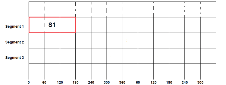
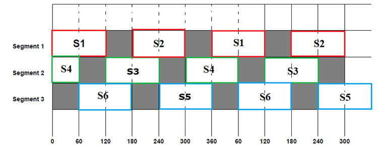
The ideal circuit is drawn before it can be divided into three segments, namely segment one, segment two & segment three, and we will use these notations in the later section of the article. Segment one consists of a pair of switches S1 and S2, segment two consists of switching pair S3 &S4, and segment three consists of switching pair S5 and S6. At any given time, both switches in the same segment should never be closed, as it leads to battery short circuits, failing the entire setup, so this scenario should be avoided at all times. In the 180-degree conduction mode, the driven conduction time of each three phase inverter circuit is precisely 180° of the fundamental period. Hence, better voltage utilisation is offered under a three-phase inverter output voltage.
Advantages of 180° Conduction:
- Maximum voltage utilisation from a DC source.
- Maximum fundamental voltage output.
- High power transfer capability.
- Used in motor drive applications.
Now let’s start switching sequence by closing the switch S1 in the first segment of the ideal circuit, and let’s name the start as 0º. Since the selected time of conduction is 180º, the switch S1 will be closed from 0º to 180º.
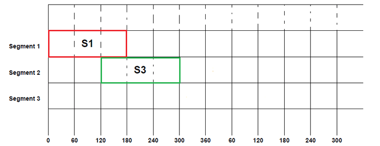
But after 120º of the first phase, the second phase will also have a positive cycle as seen in the three-phase voltage graph, so switch S3 will be closed after S1. This S3 will also be kept closed for another 180º. So S3 will be closed from 120º to 300º, and it will be open only after 300º.
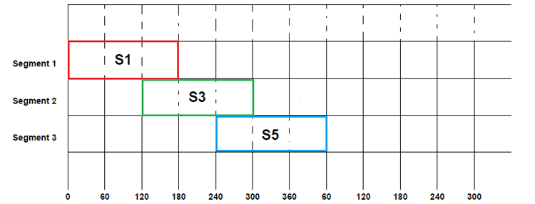
Similarly, the third phase also has a positive cycle after 120º of the second phase positive cycle, as shown in the graph at the beginning of the article. So the switch S5 will be closed after 120º S3 closing, i.e. 240º. Once the switch is closed, it will be kept closed for the next 180º before being opened, with that the S5 will be closed from 240º to 60º (second cycle).
Up until now, all we did was assume that the conduction is done once the top layer switches are closed, but for the current flow from the circuit must be completed. Also, do remember that both switches in the same segment should never be closed at the same time, so if one switch is closed, then another must be open.
To satisfy both conditions above, we will close S2, S4& S6 in a predetermined order. So, only after S1 gets opened, we will have to close S2. Similarly, S4 will be closed after S3 gets opened at 300º, and in the same way, S6 will be closed after S5 completes the conduction cycle. This cycle of switching between switches of the same segment can be seen figure below. Here S2 followsS1, S4 follows S3 and S6 follows S5.
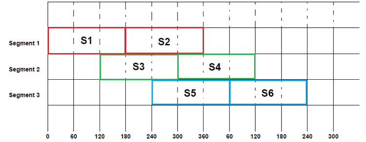
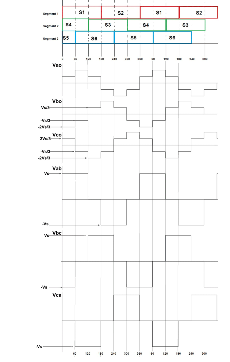
By following this symmetrical switching, we can achieve the desired three-phase voltage represented in the graph. If we fill in the beginning switching sequence in the above table, we will have a complete switching pattern for 180º conduction mode as below.
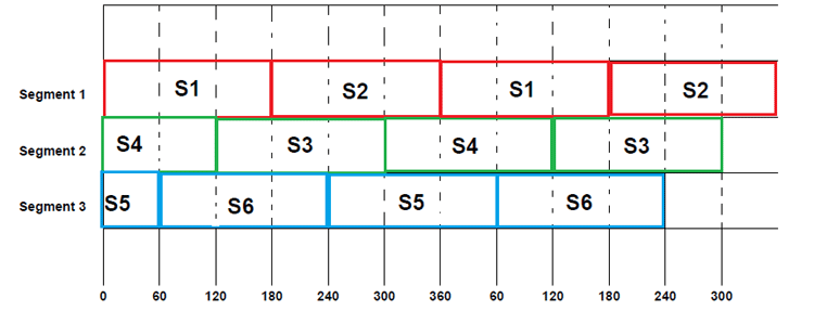
From the above table, we can understand that:
From 0-60: S1, S4 & S5 are closed and the remaining three switches are opened.
From 60-120: S1, S4 & S6 are closed, and the remaining three switches are opened.
From 120-180: S1, S3, and S6 are closed, and the remaining three switches are opened.
And the sequence of switching goes on like that. Now, let us draw the simplified circuit for each step to better understand the current flow and voltage parameters.
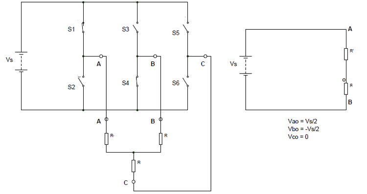
Step 1: (for 0-60) S1, S4, and S5 are closed while the remaining three switches are open. In such a case, the simplified circuit can be as shown below.
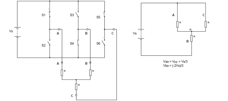
So for 0 to 60: Vao = Vco= Vs/3 ; Vbo = -2Vs/3
By using these, we can derive the line voltages as:
Vab = Vao – V bo = Vs
Vbc = Vbo – Vco = -Vs
Vca = Vco – Vao = 0
Step 2: (for 60 to 120) S1, S4, and S6 are closed while the remaining three switches are open. In such a case, the simplified circuit can be as shown below.
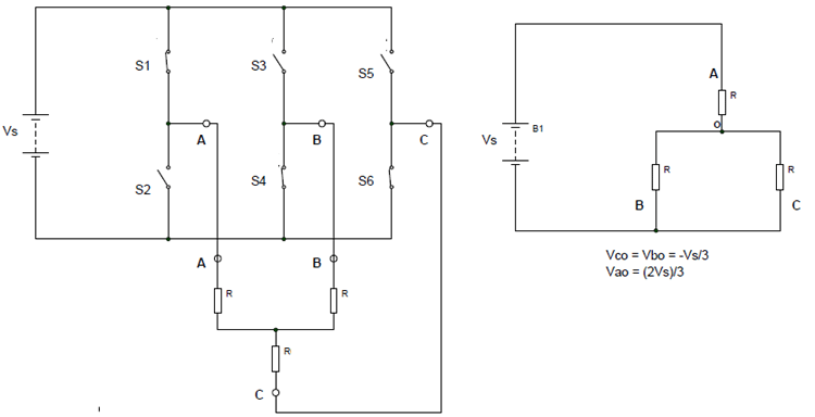
So for 60 to 120: Vbo = Vco= -Vs/3 ; Vao = 2Vs/3
By using these, we can derive the line voltages as:
Vab = Vao – Vbo = Vs
Vbc = Vbo – Vco = 0
Vca = Vco – Vao = -Vs
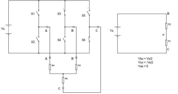
Step 3: (for 120 to 180) S1, S3, and S6 are closed while the remaining three switches are open. In such a case, the simplified circuit can be drawn as shown below.
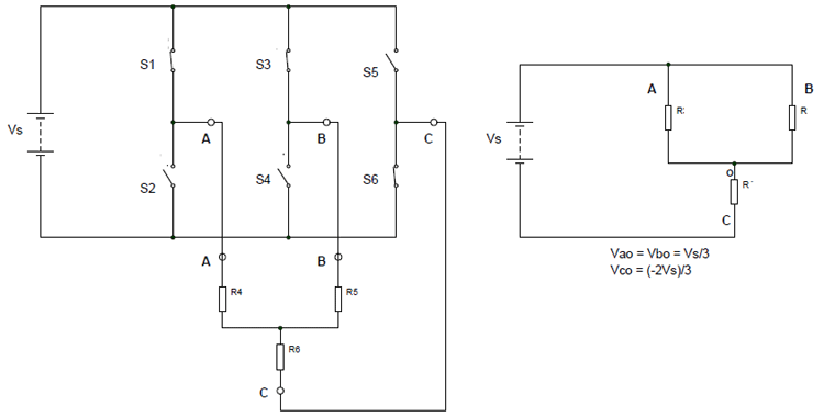
So for 120 to 180: Vao = Vbo= Vs/3 ; Vco = -2Vs/3
By using these, we can derive the line voltages as:
Vab = Vao – V bo = 0
Vbc = Vbo – Vco = Vs
Vca = Vco – Vao = -Vs
Similarly, we can derive the phase voltages and line voltages for the next steps in the sequence. And it can be shown as the figure given below:
120-Degree Conduction Mode Analysis
The 120º mode is similar to 180º in all aspects except that the closing time of each switch is reduced to 120, which was 180 before.
As usual, let’s start the switching sequence by closing the switch S1 in the first segment and setting the start number to 0º. Since the selected time of conduction is 120º, the switch S1 will be opened after 120º, so S1 was closed from 0º to 120º.
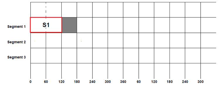
Since half a cycle of the sinusoidal signal goes from 0 to 180º, for the remaining time S1 will be open and is represented by the grey area above.
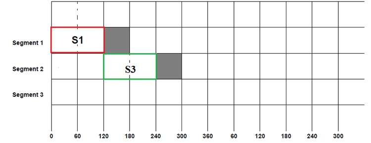
Now, after 120º of the first phase, the second phase will also have a positive cycle as mentioned before, so switch S3 will be closed after S1. This S3 will also be kept closed for another 120º. So S3 will be closed from 120º to 240º. The 120-degree conduction mode provides a different switching strategy that each switch only conducts 120° of the fundamental cycle in a multi-phase inverter configuration. As a result, the three-phase inverter output voltage characteristics and harmonic content would be different.
120° Mode Characteristics
- Possibly lower switching losses resulting from a multi-phase inverter due to fewer actively switching devices
- Different voltage utilisation ratio feature compared to the 180° mode of operation
- Different harmonic spectrum
- Simple control implementation scheme
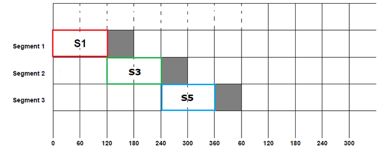
Similarly, the third phase also has a positive cycle after 120º of the second phase positive cycle, so the switch S5 will be closed after 120º of S3 closing. Once the switch is closed, it will be kept closed for the next 120º before being opened, and with that, the switch S5 will be closed from 240º to 360º
This cycle of symmetrical switching will be continued to achieve the desired three-phase voltage. If we fill in the beginning and ending switching sequence in the above table, we will have a complete switching pattern for 120º conduction mode as below.
From the above table, we can understand that:
From 0-60: S1&S4 are closed while the remaining switches are opened.
From 60-120: S1 &S6 are closed while the remaining switches are opened.
From 120-180: S3&S6 is closed while the remaining switches are opened.
From 180-240: S2&S3 are closed while the remaining switches are opened
From 240-300: S2&S5 are closed while the remaining switches are opened
From 300-360: S4&S5 are closed while the remaining switches are opened
And this sequence of steps goes on like that. Now, let us draw the simplified circuit for each step to better understand the current flow and voltage parameters of the 3 Phase Inverter circuit.
Step 1: (for 0-60) S1, S4 are closed while the remaining four switches are open. In such a case, the simplified circuit can be shown as below.
So for 0 to 60: Vao = Vs/2, Vco= 0 ; Vbo = -Vs/2
By using these, we can derive the line voltages as:
Vab = Vao – V bo = Vs
Vbc = Vbo – Vco = -Vs/2
Vca = Vco – Vao = -Vs/2
Step 2: (for 60 to 120) S1 &S6 are closed while the remaining switches are open. In such a case, the simplified circuit can be shown as below.

So for 60 to 120: Vbo =0, Vco= -Vs/2 & Vao = Vs/2
By using these, we can derive the line voltages as:
Vab = Vao – Vbo = Vs/2
Vbc = Vbo – Vco = Vs/2
Vca = Vco – Vao = -Vs
Step 3: (for 120 to 180) S3&S6 are closed while the remaining switches are open. In such a case, the simplified circuit can be shown as below.
So for 120 to 180: Vao =0, Vbo= Vs/2 & Vco = -Vs/2
By using these, we can derive the line voltages as:
Vab = Vao – V bo = -Vs/2
Vbc = Vbo – Vco = Vs
Vca = Vco – Vao = -Vs/2
Similarly, we can derive the phase voltages and line voltages for the next upcoming steps. And if we draw a graph for all the steps, then we will get something like below.
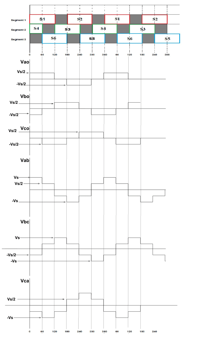
It can be seen in the output graphs of both 180º and 120º switching cases that we have achieved an alternating three-phase voltage at the three output terminals. Although the output waveform is not a pure sine wave, it does resemble the three-phase voltage waveform. This is a simple ideal circuit and approximated waveform for understanding the 3 phase inverter working. You can design a working model based on this theory using thyristors, switching, control, and protection circuitry.
Applications and Design Considerations
Careful understanding of the three-phase inverter output voltage characteristics is necessary to ensure that good application choices will be made. Each of the conduction modes will result in stepped waveforms that will approximate sinusoidal voltages. The 3 phase inverter circuit diagram could be used in a variety of working systems, including, but not limited to, the following applications:
Main Applications:
» Motor Drives: Variable frequency drives for AC motors
» UPS Systems: Uninterruptible power supply for critical loads
» Renewables: Solar and wind power conversion systems
» Grid-Tie Inverters: Connection to utility power systems
» Industrial Heating: Induction heating applications
Design Selection Criteria
| Criteria | 180° Mode Best For | 120° Mode Best For |
|---|---|---|
| Voltage Utilization | High power applications | Lower voltage requirements |
| Switching Losses | Moderate efficiency | Higher efficiency |
| Harmonic Content | Motor drive systems | Filter-sensitive loads |
| Control Complexity | Standard implementations | Simplified control |
Future Trends and Advanced Techniques
Modern 3 phase inverter working principle developments focus on improved efficiency and performance:
- PWM Techniques: Sinusoidal and space vector modulation
- Multilevel Topologies: Reduced harmonic distortion
- Digital Control: Microcontroller and DSP-styled systems
- Wide Bandgap Devices: SiC and GaN semiconductors for improved efficiency
Conclusion
The three phase inverter circuit is a basic power electronic system needed in many modern AC applications. Both 180-degree and 120-degree conduction modes have inherent benefits, depending on application needs. Knowing the 3 phase inverter circuit diagram and its working principles is important as it allows an Engineer to design a well-functioning power conversion system.
Frequently Asked Questions on Three Phase Inverter Circuit
⇥ 1. How do the 180° and 120° conduction modes in three phase inverters differ?
In 180° mode, there are all three switches are active simultaneously for part of the cycle (180°), therefore allowing them to utilise higher voltage for effective voltage utilisation. In 120° mode, only two switches in each of the three parts of the full cycle (120°) are active at a time, which results in a lower number of switching losses but also reduced effective voltage.
⇥ 2. How many switches are used in a three phase inverter circuit?
In a three phase inverter circuit, there are six power switches, configured in three segments (legs). Each leg is constructed using two switches that are operated complementarily to ensure no short circuit occurs across the DC source. The switches will typically be either a thyristor, a MOSFET or an IGBT, depending on the operational requirements.
⇥ 3. What happens if the two switches in the same segment close at once?
When two switches in the same segment close, it directly short-circuits the DC source; current surges through and destroys the switches and sometimes the power supply as well. This wrongful conduct, called "shoot-through", must be prevented. It can be done using some control logic or by implementing dead-time.
⇥ 4. Which conduction mode makes better use of voltage?
The 180° conduction mode gives improved utilisation of voltage than the 120° mode. In 180° mode, fundamental voltage output is greater as three switches simultaneously conduct for more times, utilising the provided DC source voltage to the maximum extent for transferring power.
⇥ 5. Why are the three phases shifted by 120° in a three phase inverter?
The 120-phase displacement provides a balanced three-phase operation in which the vector addition of the three-phase voltages results in zero. This vector produces the rotating magnetic field in motors and continuous power transfer in three-phase systems, both necessary for unidirectional operation and lower torque ripple.
⇥ 6. What are the general applications of three-phase inverters?
Three-phase inverters are, moreover, used to feed variable frequency drives (VFDs) for motor control, uninterruptible power supplies (UPS) for the continuity of load power supply, renewable energy systems for solar and wind converters, industrial heating processes, and grid-tie inverters for connecting distributed generation to utility grids.
Related Inverter & Power Electronics Projects
Develop a deeper understanding of inverter design and control by exploring these additional builds. From generating pure sine waves with microcontrollers to experimenting with PWM-based switching and higher-capacity inverter circuits, these projects highlight practical approaches to power conversion and waveform generation in real-world applications.

In this project, we are going to build a pure sine wave inverter with a rating of 300W or 800VA. It outputs a pure sinewave at line frequency.

PWM Inverter Circuit using TL494
In this project I will be building a simple modified square wave PWM inverter circuit by using the popular TL494 IC and explain the pros and cons of such an inverters and at the end.

Pure Sine Wave Inverter Using Arduino
In this article I make a simple pure sine wave inverter circuit using Arduino, and explain the working principle of the circuit.
thank you for your good information
Thank you for explaining the same waveform about PWM or for introducing a source

You explained clearly.