

Power supplies can be classified into two broad categories: AC power supply and DC power supply. Since only AC power can be generated economically, most electrical machines run on AC power. However, the standard voltage and frequency from generating stations may not suit certain industrial machines. This is where power electronic converters like inverters and cycloconverters become essential for frequency and voltage conversion.
In this comprehensive guide, we'll explore cycloconverter types, cycloconverter working principles, detailed circuit diagrams, and real-world applications of cycloconverters, and the advantages to help you understand this critical power electronics component.
What is a Cycloconverter? - Quick Definition
A cycloconverter (CCV) is a power electronic device that converts AC power of one frequency directly into AC power of a different (usually lower) frequency without using an intermediate DC link. It enables precise speed control of AC motors and is widely used in industrial applications like steel mills, ship propulsion, and heavy machinery.
Table of Contents
- What is a Cycloconverter?
- └ Key Characteristics
- Cycloconverter Block Diagram
- Essential Components
- Why do we need Cycloconverters?
- Types of Cycloconverters
- └ Complete Classification
- Advantages
- Basic Principle behind Cycloconverters
- Single Phase to Single Phase Cycloconverters
- └ Waveform Analysis
- Three Phase to Single Phase Cycloconverter
- Three Phase to Three Phase Cycloconverter
- Applications of Cycloconverter
- └ Primary Industrial Applications
- └ Why Cycloconverters
What is a Cycloconverter? - Detailed Explanation
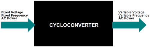
A cycloconverter (also called a cycloinverter) converts a constant voltage, constant frequency AC waveform to another AC waveform of a different frequency by synthesising the output waveform from segments of the AC supply without an intermediate DC link.
Key Characteristics of Cycloconverters:
- Direct frequency conversion: No DC link stage required
- High efficiency: Typically 95-98% due to direct conversion
- Bidirectional power flow: Can operate in both motoring and regenerative modes
- Variable output frequency: From 0 Hz to 1/3 of the input frequency
- Four-quadrant operation: Complete speed and torque control
The conversion process uses power electronic switches like thyristors (SCRs), IGBTs, or MOSFETs arranged in positive and negative converter groups. Each group conducts during alternate half-cycles, enabling bidirectional power flow and precise frequency control.
Cycloconverter Block Diagram & System Components
Essential Components in the Cycloconverter Block Diagram
| Section | Components |
|---|---|
| Input Section |
|
| Converter Groups |
|
| Control System |
|
| Output Section |
|
How Does a Cycloconverter Work? - Step-by-Step Working Principle
Understanding the cycloconverter working principle is crucial for power electronics engineers. The operation involves controlled switching of thyristors to synthesise the desired output frequency from the input AC supply. If you are completely new to thyristors, check out our article on what a thyristor is and how it works.
Cycloconverter Working Process:
- Input AC Supply: Three-phase or single-phase AC at fixed frequency (50/60 Hz)
- Positive Converter Group: Conducts during the positive half-cycles of the desired output
- Negative Converter Group: Conducts during the negative half-cycles of the desired output
- Control Circuit: Generates firing pulses based on desired output frequency
- Output Synthesis: Combines segments to create a variable frequency AC output
Firing Angle Control in Cycloconverters Working:
The output frequency and voltage in the cycloconverter working are controlled by varying the firing angle (α) of thyristors. Key control parameters include:
- Firing Angle (α): Controls output voltage magnitude
- Switching Frequency: Determines output frequency (fo = fin × switching ratio)
- Pulse Width: Affects harmonic content and power quality
Mathematical Relationship in Cycloconverter Working:
Output Frequency: fo = (m/n) × fin
Where: m = number of output cycles, n = number of input cycles, fin = input frequency
Why Do We Need Cycloconverters?
Okay, now we know that Cycloconverters convert AC power of fixed frequency to AC Power of variable Frequency. But why do we need to do that? What is the advantage of having an AC power supply with variable Frequency?
The answer to this question is Speed Control. Cycloconverters are extensively used for driving large motors like the one used in Rolling mills, Ball mills, Cement kils, etc. The output frequency of a Cycloconverter can be reduced to zero, which helps us to start very large motors with full load at minimum speed and then gradually increase the speed of the motor by increasing the output Frequency. Before the invention of Cycloconverters, these large motors had to be unloaded completely, and then, after starting the motor, it had to be loaded gradually, which resulted in time and manpower consumption. If this interests you, you should also check out Variable Frequency Drives (VFDs). Both VFDs and cycloconverters serve a similar purpose, that is, they use frequency control for motor speed.
Types of Cycloconverters - Complete Classification Guide
Based on the output frequency and number of phases in the input AC power source, the types of cycloconverters can be classified as follows
1. Step-Up Cycloconverters
2. Ste-Down Cycloconverters
- Single-Phase to Single-Phase Cycloconverter
- Three-Phase to Single-Phase Cycloconverter
- Three-Phase to Three-Phase Cycloconverter
Step-Up Cycloconverters: Step-Up CCV, as the name suggests, this type of CCV provides an output frequency greater than the input frequency. But it is not widely used since it does not have many practical applications. Most applications will require a frequency less than 50Hz, which is the default frequency here in India. Also, Step-Up CCV will require forced commutation, which increases the complexity of the circuit.
Step-Down Cycloconverters: Step-Down CCV, as you might have already guessed, just provides an output frequency which is less than the input frequency. These are most commonly used and work with the help of natural commutation, hence comparatively easy to build and operate. The Step-Down CCV is further classified into three types, as shown below. We will look into each of these types in detail in this article.
Complete Classification of Types of Cycloconverters
| Classification Basis | Type | Characteristics | Applications |
|---|---|---|---|
| Frequency Relation | Step-Up Cycloconverter | fo > fin (rarely used) | Research applications |
| Step-Down Cycloconverter | fo < fin (most common) | Industrial motor drives | |
| Phase Configuration | Single Phase to Single Phase | 1φ input → 1φ output | Small motors, testing |
| Three Phase to Single Phase | 3φ input → 1φ output | Single phase motor drives | |
| Three Phase to Three Phase | 3φ input → 3φ output | Large industrial motors |
Advantages of Cycloconverters
» Maximum Efficiency: 95-98% because of direct conversion
» No DC Link: No huge capacitors and reactors
» Regenerative Operations: Recovery of energy
» Very Good Low Speed Torque: Full torque from zero speed
» Four Quadrant Operation: Full control of speed and direction
» High Capable Power: For applications of 100+ MW
» Bidirectional Power Flow: Works as a motor and or generator
» Smooth Speed Control: Varying frequencies uniformly
Basic Principle behind Cycloconverters:
Although there are three different types of Cycloconverters, their working principles are very similar except for the number of power electronic switches present in the circuit. For instance, a single phase to single phase CCV will have only 6 power electronic switches (SCR’s) while a three phase CCV might have up to 32 switches.
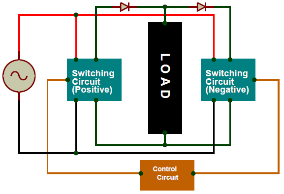
The bare minimum for a Cycloconverter is shown above. It will have a Switching circuit on either side of the Load, one circuit will function during the positive half cycle of the AC power source, and the other circuit will function during the negative half cycle. Normally, the switching circuit will be demonstrated using SCR as a power electronic device, but in modern CCV, you can find the SCR being replaced by IGBTs and sometimes even MOSFETS.
The switching circuits will also need a control circuit, which instructs the Power electronic device when to conduct and when to turn off. This control circuit will normally be a Microcontroller and might also have feedback from the output to form a closed-loop system. The user can control the value of output frequency by adjusting the parameters in the control circuit. The diodes in the above diagram are used to represent the direction of flow of current. The positive switching circuit always sources current into the load, and the negative switching circuit always sinks current from the load.
Single Phase to Single Phase Cycloconverters
The single phase to single phase cycloconverter is the simplest form among all types of cycloconverters. The Single Phase to Single Phase CCV is very rarely used, but to understand the operation of a CCV, it should first be studied so that we can understand the Three Phase CCV. The Single Phase to Single Phase CCV has two pairs of full-wave rectifier circuits, each consisting of four SCR. One set is placed straight while the other is placed in an anti-parallel direction, as shown in the picture below. This type of configuration is called an H-Bridge circuit. You can read more on the H-Bridge Motor Driver Circuit if you are interested.
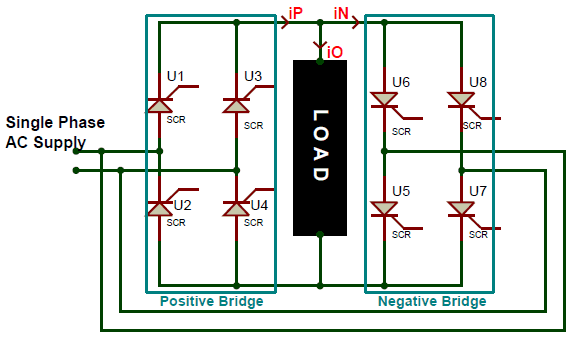
All the gate terminals of the SCR’s will be connected to a control circuit, which is not shown in the circuit above. This control circuit will be responsible for triggering the SCRs. To understand the working of the circuit, let us assume that he input AC supply is of 50Hz frequency, the Load is a pure resistive load, and the firing angle of the SCR (α) is 0°. Since the firing angle is at 0°, the SCR, when turned on, will act like a diode in the forward direction, and when turned off, will act like a diode in the reverse direction. Let us analyse the waveform below to understand how frequency is stepped down using a CCV
Waveform Analysis for Single Phase to Single Phase Cycloconverter
The waveform demonstrates how single phase to single phase cycloconverter achieves frequency conversion by selectively using input AC segments.
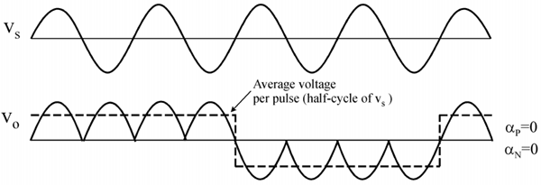
The waveform of the supply voltage frequency is denoted by Vs, and the waveform of the output voltage frequency is denoted by Vo. Here we are trying to convert the supply voltage frequency to 1/4th of its value. So, to do that for the first two cycles of the supply voltage, we will use the positive Bridge rectifier, and for the next two cycles, we will use the negative bridge rectifier. Thus, we have four positive pulses in the positive region and then four in the negative region, as shown in the output frequency waveform Vo. The current waveform for this circuit will be the same as the voltage waveform since the load is assumed to be purely resistive. The magnitude of the waveform will change based on the value of the resistance of the load.
The output frequency is represented using the dotted line on the Vo waveform, since it changes polarity only for every two cycles of the input waveform. The output frequency is 1/4th of the input frequency. In our case, for an input frequency of 50Hz, the output frequency will be (1/4 * 50), around 12.5Hz. This output frequency can be controlled by varying the triggering mechanism in the control circuit.
Three Phase to Single Phase Cycloconverter - Advanced Configuration
The three phase to single phase cycloconverter represents a significant advancement in cycloconverter technology. The Three Phase to Single Phase CCV is also similar to the Single Phase to Single Phase CCV, but in this case, the input voltage is a 3 Phase supply and the output voltage is a Single Phase supply with variable frequency. The circuit also looks very similar, except we will need 6 SCR in each set of Rectifier since we have to rectify the 3 Phase AC voltage.
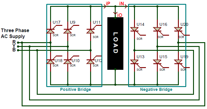
Again, the gate terminals of the SCR will be connected to the control circuit for triggering them, and the same assumptions are made again to understand the working easily. Also, there are two kinds of Three Phase to Single Phase CCVs; the first type will have a half-wave rectifier for both Positive and Negative Bridge, and the second type will have a full-wave rectifier, as shown above. The first type is not used often because of its poor efficiency. Also, in a full-wave type, both the bridge rectifiers can generate voltages in both polarities, but the positive converter can supply current (source) only in the positive direction, and the negative converter can drain current only in the negative direction. This allows the CCV to operate in four Quadrants. These four quadrants are (+V, +i) and (-V, -i) in rectification mode and (+V, -i) and (-V,-i) in inversion mode. The three phase to single phase cycloconverter employs two 6-pulse rectifier bridges (12 SCRs total) connected in anti-parallel configuration.
Three Phase to Three Phase Cycloconverter - Industrial Standard
The Three Phase to Three Phase CCV are the most used one since it can drive Three Phase loads like motors directly. The Load for a Three Phase CCV will normally be a Three Phase Star connected load, like the stator winding of a Motor. These converters take in Three Phase AC voltage with a fixed frequency as input and provide Three Phase AC voltage with Variable frequency. The three phase to three phase cycloconverter represents the most advanced and widely used configuration in heavy industrial applications.
There are two types of Three Phase CCV, one which has a half-wave converter and the other with a full-wave converter. The Half-wave converter model is also called the 18-thyristor Cycloconverters or the 3-pulse Cycloconverters. The full wave converter is called a 6-pulse Cycloconverters or 36-thyristor Cycloconverters. A 3-pulse Cycloconverter is shown in the picture below
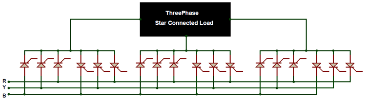
Here we have six sets of Rectifiers, of which two are allocated for each phase. The working of this CCV is similar to single phase CCV, except here the rectifiers can rectify only half the wave, and the same happens for all three phases. The three phase to three phase cycloconverter working principle involves six independent rectifier bridges (two per output phase) that create a balanced three-phase output with precise frequency and amplitude control.
Frequently Asked Questions (FAQs) about Cycloconverters
⇥ What is the main advantage of a cycloconverter?
The main advantage of a cycloconverter is direct frequency conversion without a DC link, resulting in high efficiency (95-98%), bidirectional power flow, and excellent speed control for large AC motors. This makes them ideal for heavy industrial applications requiring precise torque control.
⇥ Why is a cycloconverter used in ship propulsion?
Cycloconverters are used in ship propulsion because they provide smooth speed control from zero to maximum RPM, high efficiency at variable speeds, and regenerative braking capability. They can handle the large power requirements (up to 100 MW) needed for ship motors while maintaining excellent dynamic response.
⇥ What are the main limitations of a cycloconverter?
Key limitations include: output frequency limited to 1/3 of input frequency, high harmonic content requiring filters, complex control circuits, higher cost compared to simple inverters, and potential for circulating currents in some configurations.
⇥ How does a cycloconverter control motor speed?
Cycloconverter controls motor speed by varying the output frequency through firing angle control. By adjusting when thyristors are triggered, the output frequency can be varied from 0 Hz (motor stopped) to the maximum rated frequency, providing smooth speed control with high torque at low speeds.
⇥ What is the difference between a cycloconverter and an inverter?
A cycloconverter converts AC to AC directly without a DC link, while an inverter converts DC to AC. Cycloconverters offer bidirectional power flow and higher efficiency but are limited in output frequency. Inverters are more versatile in frequency range but require a rectification stage.
⇥ What are the primary types of cycloconverters utilised in the industry?
There are three general types of cycloconverters: single phase to single phase (utilised in testing applications), three phase to single phase (typical for medium power drives), and three phase to three phase, which are for significant heavy industrial applications. They are reported based on the frequency relationship as either step-up (only seldom used) or step-down cycloconverters (more typical use).
⇥ How do recent cycloconverters achieve a high efficiency and reliability?
Recent cycloconverters achieve efficiencies in the 95-98% range by using an architecture that allows direct AC-to-AC conversions, which removes DC link losses with a very low switching losses that can be accomplished by using advanced IGBT technology, while also using highly optimised control algorithms that minimises harmonics (which is usually specific to cycloconverters), and the experience of engineers harnessed from accumulating the sophisticated protection systems that enables the operator to rely on both high efficiency and reliable strategy as a precautionary means! The implementation of vector control and advanced digital signal processing can expand the underlying physiological and further improve both performance and reliability to modern industries.
Cycloconverter vs Other Power Electronic Converters
Understanding the differences between cycloconverters and other power electronic devices helps in selecting the right converter for specific applications.
| Parameter | Cycloconverter | PWM Inverter | Matrix Converter |
|---|---|---|---|
| Conversion Type | AC to AC (Direct) | DC to AC | AC to AC (Direct) |
| DC Link Required | No | Yes | No |
| Efficiency | 95-98% | 92-95% | 95-97% |
| Output Frequency Range | 0 to fin/3 | 0 to 400+ Hz | 0 to fin |
| Power Rating | Very High (MW range) | Low to High | Medium |
| Harmonic Distortion | High (requires filters) | Low (with PWM) | Medium |
| Cost | High | Medium | High |
| Best Applications | Large motors, mills, ships | General purpose drives | Aerospace, research |
When to Choose a Cycloconverter:
- High power applications (above 1 MW)
- Low speed, high torque requirements
- Regenerative operation needed
- Maximum efficiency is a priority
- Bidirectional power flow required
Applications of Cycloconverter - Real-World Industrial Use Cases
Applications of cycloconverters span across heavy industries where precise speed control, high efficiency, and reliable operation are critical. Cycloconverters find extensive use in heavy industrial applications where precise speed control and high efficiency are critical. Here are the major application areas:
Primary Industrial Applications
1. Steel and Metal Processing:
- Rolling Mills: Precise speed control for steel rolling operations
- Grinding Mills: Variable speed grinding with high torque
- Tube Mills: Consistent product quality control
2. Marine Applications:
- Ship Propulsion Systems: Main propulsion motors up to 100 MW
- Thruster Motors: Dynamic positioning systems
- Pump Drives: Ballast and cargo pump control
3. Mining and Extraction:
- Mine Winders: Elevator and conveyor systems
- Crushers: Variable speed rock crushing
- Conveyor Belts: Material handling systems
4. Power Systems:
- HVDC Power Lines: AC-DC-AC conversion stations
- Static VAR Generators (SVG): Power factor correction
- Grid Frequency Control: Power system stabilisation
5. Specialised Applications:
- Aircraft Power Supply: Variable frequency power generation
- Heavy Washing Machines: Industrial laundry equipment
- Test Equipment: Motor testing and research facilities
Why Cycloconverters Excel in These Applications:
These applications benefit from the cycloconverter's unique capabilities: high power handling (MW range), excellent low-speed torque, regenerative operation for energy recovery, and precise speed control, High Reliability and Four-Quadrant Operation without mechanical gearboxes.
This comprehensive guide on cycloconverters is written by power electronics experts with extensive experience in industrial applications.
Practical Projects with Converters
For a deeper understanding of how these converters are applied, explore the project links listed below.
 and Constant Voltage (CV) Control - Schematics, PCB, Parts List, and Working")
In this article, we will be learning about the features and working of the XL4015, which is a 5A 180KHz 36V Buck DC to DC Converter. Here we will desolder all the components from the module, completely reverse engineer the schematic and make the PCB from it, so that we can order the components and make the PCB ourselves.

Simple Square Wave to Sine Wave Converter
In this project, we will discuss how a square wave to sine wave converter circuit works and how it can be built using simple passive electronics. You can also check out other waveform generator circuits listed below.

An Overview of Dual Converters
Now we learn about Dual Converters, which can convert AC to DC and DC to AC at the same time. As the name suggests, Dual Converter has two converters, one converter works as a rectifier (Converts AC to DC) and the other converter works as an inverter (converts DC into AC).
