
At the outset, driving a motor might seem like an easy task – just hook the motor up to the appropriate voltage rail and it will start rotating. But this is not the perfect way to drive a motor, especially when there are other components involved in the circuit. Here, we will discuss one of the most commonly used and efficient ways to drive DC motors, the H-Bridge circuit. Creating a good H-bridge motor driver circuit using MOSFET is important for accurate control of DC motors in robotic and automation projects. This guide will provide fundamental theory, design, and construction of an H-bridge MOSFET driver circuit with detailed schematics and operation principles.
Table of Contents
- Why an H-Bridge Motor Driver Circuit?
- └ Motor Driving Methods Comparison
- Understanding DC Motor Driving Fundamentals
- └ PWM Motor Control: The Efficiency Solution
- H-Bridge Motor Driver Circuit: Complete Solution
- H-Bridge Motor Driver Circuit Working Principle
- Component Selection
- Schematic
- Detailed Working Explanation
- Troubleshooting
Why an H-Bridge Motor Driver Circuit?
- Allow bi-directional motor control with a single power supply
- Allows variable speed control with PWM modulation
- Higher efficiency than a linear motor driver
- Ability to provide electronic braking
- Scalable design for any motor size
Motor Driving Methods Comparison
| Method | Efficiency | Speed Control | Direction Control | Cost |
| Direct Connection | High | None | Manual | Low |
| Linear Regulator | Low | Good | Manual | Medium |
| H-Bridge MOSFET | Very High | Excellent | Electronic | Medium |
Understanding DC Motor Driving Fundamentals
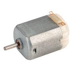
The most common type of motor you might come across in hobbyist circles for low-power applications is the 3V DC motor shown below. This kind of motor is optimised for low-voltage operation from two 1.5V cells. While connecting a DC motor directly to a voltage source seems straightforward, professional applications require sophisticated H-bridge DC motor control systems.
And running it is as simple as connecting it to two cells – the motor fires up instantly and runs as long as the batteries are connected. While this kind of setup is good for ‘static’ applications like a miniature windmill or fan, when it comes to a ‘dynamic’ application like robots, more precision is needed – in the form of variable speed and torque control.
Decreasing the voltage across the motor decreases the speed, and a dead battery results in a slow motor, but if the motor is powered from a rail common to more than one device, a proper driving circuit is needed.
This can even be in the form of a variable linear regulator like the LM317 – the voltage across the motor can be varied to increase or decrease speed. If more current is needed, this circuit can be built discreetly with a few bipolar transistors. The biggest drawback with this kind of setup is the efficiency – just like with any other load, the transistor dissipates all the unwanted power.
PWM Motor Control: The Efficiency Solution
The solution to this problem is a method called PWM or pulse width modulation. Here, the motor is driven by a square wave with an adjustable duty cycle (the ratio of on time to the period of the signal). The total power delivered is proportional to the duty cycle. In other words, the motor is powered for a small fraction of the time period, so over time, the average power to the motor is low. With a 0% duty cycle, the motor is off (no current flowing); with a duty cycle of 50% the motor runs at half power (half the current draw), and 100% represents full power at maximum current draw.
This is implemented by connecting the motor high side and driving it with an N-channel MOSFET, which is driven again by a PWM signal. A basic N-channel MOSFET H-bridge implementation uses a single MOSFET for low-side switching.

This has some interesting implications – a 3V motor can be driven using a 12V supply using a low duty cycle since the motor sees only the average voltage. With careful design, this eliminates the need for a separate motor power supply.
What if we need to reverse the direction of the motor? This is usually done by switching the motor terminals, but this can also be done electrically.
One option could be to use another FET and a negative supply to switch directions. This requires one terminal of the motor to be permanently grounded and the other connected to either the positive or negative supply. Here, the MOSFETs act like an SPDT switch.
However, a more elegant solution exists.
H-Bridge Motor Driver Circuit: Complete Solution
The H-bridge motor driver circuit diagram represents the ultimate solution for bidirectional motor control.
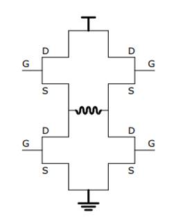
This circuit is called an H-bridge because the MOSFETs form the two vertical strokes and the motor forms the horizontal stroke of the alphabet ‘H’. It is the simple and elegant solution to all motor driving problems. The direction can be changed easily, and the speed can be controlled.
H-Bridge Motor Driver Circuit Working Principle
The H-bridge motor driver circuit working principle relies on diagonal MOSFET pair activation. In an H-bridge configuration, only the diagonally opposite pairs of MOSFETs are activated to control the direction, as shown in the figure below:
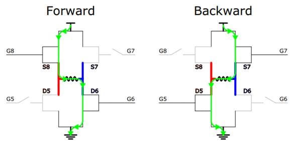
When activating one pair of (diagonally opposite) MOSFETs, the motor sees current flow in one direction, and when the other pair is activated, the current through the motor reverses direction.
The MOSFETs can be left on for full power or PWM-ed for power regulation, or turned off to let the motor stop. Activating both bottom and top MOSFETs (but never together) breaks the motor.
Another way to implement an H-Bridge is using 555 timers, which we discussed in a previous tutorial.
Component Selection for H-Bridge MOSFET Driver Circuit
- DC motor
- 2x IRF3205 N-channel MOSFETs or equivalent
- 2x IRF5210 P-channel MOSFETs or equivalent
- 2x 10K resistors (pulldown)
- 2x 100uF electrolytic capacitors (decoupling)
- 2x 100nF ceramic capacitors (decoupling)
For the Control Circuit
- 1x 555 timer (any variant, preferably CMOS)
- 1x TC4427 or any appropriate gate driver
- 2x 1N4148 or any other signal/ultrafast diode
- 1x 10K potentiometer (timing)
- 1x 1K resistor (timing)
- 4.7nF capacitor (timing)
- 4.7uF capacitor (decoupling)
- 100nF ceramic capacitor (decoupling)
- 10uF electrolytic capacitor (decoupling)
- SPDT switch
H bridge Schematic for Motor Control
This professional H-bridge motor driver circuit diagram handles motors up to 20A and 40V with proper heatsinking. Now that we’ve got the theory out of the way, it’s time to get our hands dirty and build an H-bridge motor driver. This circuit has enough power to drive medium-sized motors up to 20A and 40V with proper construction and heatsinking. Some features have been simplified, like the usage of a SPDT switch to control the direction.
Also, the high-side MOSFETs are P-channel for simplicity. With the appropriate driving circuit (with bootstrapping), N-channel MOSFETs could also be used.
The complete circuit diagram for this H-Bridge using MOSFETs is given below:

Detailed Working Explanation
1. The 555 Timer
The timer is a simple 555 circuit that generates a duty cycle from around 10% to 90%. The frequency is set by R1, R2 and C2. High frequencies are preferred to reduce audible whining, but this also means that a more powerful gate driver is needed. The duty cycle is controlled by potentiometer R2. Learn more about using a 555 timer in astable mode here.
This circuit can be replaced by any other PWM source, like an Arduino.
2. Gate Driver
The gate driver is a standard two-channel TC4427, with 1.5A sink/source per channel. Here, both the channels have been paralleled for more driving current. Again, if the frequency is higher, the gate driver needs to be more powerful.
The SPDT switch is used to select the leg of the H-bridge which controls the direction.
3. H-Bridge
This is the working part of the circuit that controls the motor. The MOSFET gates are normally pulled low by the pulldown resistor. This results in both the P-channel MOSFETs turning on, but this is not a problem since no current can flow. When the PWM signal is applied to the gates of one leg, the N and P-channel MOSFETs are turned on and off alternately, controlling the power.
Troubleshooting Common H-Bridge Issues
| Problem | Symptoms | Possible Causes | Solutions |
| Motor doesn't run | No rotation, no current draw | Gate drive failure, supply issues | Check gate voltages, verify supply |
| Overheating MOSFETs | Hot components, reduced performance | High RDS(on), inadequate heatsinking | Add heatsinks, check MOSFET selection |
| Motor runs only one direction | Unidirectional operation | Failed MOSFET, gate drive issues | Test individual MOSFETs, check gate signals |
| Blown fuses | Immediate fuse failure | Short circuit, shoot-through | Check for damaged MOSFETs, verify dead time |
H-Bridge Circuit Construction Tips
The biggest advantage of this circuit is that it can be scaled to drive motors of all sizes, and not only motors – anything else that needs a bidirectional current signal, like sine wave inverters.
When using this circuit, even at low powers, proper localised decoupling is a must unless you want your circuit to be glitchy.
Also, if constructing this circuit on a more permanent platform like a PCB, a large ground plane is recommended, keeping the low current parts away from the high current paths.
This in-depth reference design for H-bridge motor driver circuits using MOSFET is a truly professional-level control method for motors. If you are building the circuit as a hobby project, or developing a professional product for commercial purposes, this H bridge schematic for motor control will provide robust, reliable and efficient bidirectional motor control. Finally, do not forget that successful H-bridge DC motor control requires paying careful attention to PCB layout and component placement and proper testing after building.
So this simple H-Bridge circuit is the solution for many motor driving problems, power management and efficiency.
Frequently Asked Questions about H-bridge MOSFET Driver Circuit
⇥ Q1: What is the maximum current rating for this H-bridge motor driver design?
It is able to handle the continuous current rating of 20A, provided that you have good heatsinking and component selection. For higher currents, select larger MOSFETs with a lower RDS-on, use better thermal management, add some kind of current-sensing protection, and possibly use parallel MOSFETs.
⇥ Q2: Can I control motor speed without PWM in an H-bridge circuit?
You can with linear voltage regulation if you want to, but it is encouraged to use PWM at all times with H-bridge motor drivers and systems. The efficiency rate with PWM is superior, over 90% versus ~50% for linear. Secondly, PWM provides precise control of speed, much more so than voltage reduction for linear methods. Third, you will create less heat with PWM with H-bridge motor drivers and H-bridge systems. Finally, PWM will maintain full torque at low speeds versus voltage reductions.
⇥ Q3: What are the advantages of using P-channel high-side MOSFETs in an H-bridge circuit?
P-channel high-side MOSFETs would have a simpler gate drive circuitry because bootstrap circuits or a separate isolated supply are not necessary. They do, however, usually have a higher RDS-on value and cost more than the N-channels. The highest efficiency value usually requires an N-channel with a proper bootstrap gate drive, but if it can be done without sacrificing efficiency, you could save cost and space with a P-channel alternative.
⇥ Q4: Describe the function of an H-bridge motor driver circuit.
An H-bridge motor driver circuit is made up of four MOSFET devices in a switching topology. The functionality of the H-bridge motor controller circuit is equivalent to the functionality of a single-pole double-throw toggle switch. In the H-bridge configuration, the current switches diagonally across MOSFET devices, switching the direction of current flow in the clockwise or counterclockwise direction based upon whether the circuit is in forward or reverse operation when the MOSFET devices are turned on.
⇥ Q5: Why would you use MOSFETs in an H-bridge over bipolar transistors?
MOSFETs really do offer a number of advantages over bipolar transistors in an H-bridge circuit because they generally have lower on-resistance (RDS-on) and faster switching frequency, better thermal characteristics, and being voltage-controlled devices that do not draw gate current are some of the inherent advantages of MOSFETs. These advantages translate into better efficiency and thermal current-handling capability when compared with bipolar transistors.
⇥ Q6: Can this H-bridge configuration work for other motor voltages and other types of motors?
The principles of the H-bridge should allow it to easily scale with motor voltages from 6V-40V, and to other types of motors such as brush type DC motor, DC gear motor, or linear actuator. Just remember to scale the MOSFET ratings, gate driver capacities, and PWM parameters accordingly. For other types of motors, just be aware of extra requirements such as encoder feedback for servo control, etc.
Hands-on Projects Using Motor Drivers
Several of our earlier projects were designed using these Motor Drivers. For detailed insights, please check the links provided below.

How to use the L298N Motor Driver with Arduino?
In this Arduino motor control tutorial, we’ll guide you through interfacing the L298N with Arduino, understanding its working principle, and writing code to run a DC motor forward and backwards with variable speed control.

Stepper Motor Control with A4988 Stepper Motor Driver and Arduino UNO
In this A4988 stepper motor driver tutorial, we'll be looking at how to interface and connect the A4988 stepper motor driver module to Arduino and go over the basic principles of stepper motors, A4988 stepper motor driver pinout, wiring connections, and programming examples.

Control DC Motor with Arduino and L293D Motor Driver IC
And one of the best ways to do it is by using a L293D motor driver IC, because it's cheap, easy to use and with a bit of PWM support, it can control both speed and direction. This is why in this tutorial, we will be using the popular L293D motor driver IC to simply control the speed and direction of the motor.

Nice idea for learning H-bridge circuits, your logic is right on; some major things you may have missed.
Shoot thru occurs when both the upper and lower MOSFETs turn on at the same time. With your circuit as shown this will happen at the transition where one is turning on the is turning off. Note: the higher the VCC the worse it will get, causing excess heating of the MOSFETs and eventually failure to occur.
Examine the Vgs of both upper and lower devices over the full gate voltage swing. You will fine you have them both in the partially enhancement mode where both are trying to conduct. The slower the rise and fall time of the gate the worse this will be. This will create some huge current spikes.
What is shown on the breadboard will work because of the limiting impedance of the interconnections. If this is built for say 20A 40V you will be blowing MOSFETs. The primary failure will be either shoot through or VGS over voltage.
The Vgs of both devices is +- 20V which is way short of the max 40V suggested. At approximately 3V Vgs both devices are turning on. There is also the Miller Capacitor effect which will also slow down the switching time however the TC4427 (4.5 - 18V) is a good choice to solve this problem.
Do continue with this, you have made a great start.
Gil