

There are lots of factories and plants in the world which use a different type of high power motors. Due to the high power consumption, the factories and plants end up paying a high amount of energy bills. To overcome the high power consumption and to increase the efficiency, VFD was introduced four decades ago but the circuitry was not strong enough.
VFD is the short form of a Variable Frequency Drive or adjustable frequency drive. The frequency determines the motor RPM and by controlling the AC frequency the motor RPM can be controlled. Different types of VFDs are available in the electronics and electrical market ranging from small motor related applications to the high power induction motors. Other than the three-phase VFDs, single phase VFDs are also available.
VFD Circuit and Its Operation
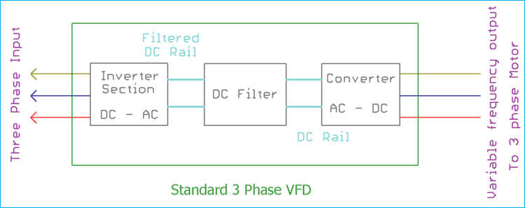
A VFD circuit consists of three parts.
1.The rectifier section
2.The filter section
3.The switching or inverter section.
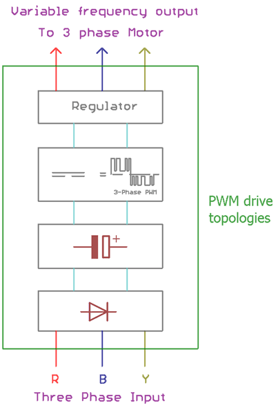
In the below image the three sections are shown inside a block diagram. This is a basic circuit block diagram of a three phase VFD.
Rectifier Section of VFD Circuit
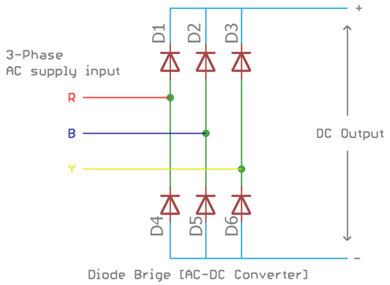
rectifier section uses 6 diodes. The diodes D1, D2, and D3 are connected with the positive rail and the diode D4, D5 and D6 are connected with the negative rail. Those 6 diodes act as a diode bridge which converts the three-phase AC signal into a single DC rail. The three-phase R, B, and Y are connected across the diode. Depending on the sinusoidal wave polarity the diodes gets forward biased or reverse biased thus providing a positive pulse or a negative pulse in both positive and negative rail.
To learn more about how rectifier works, just follow the link.
Filter Section of VFD Circuit
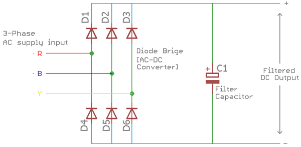
As we know the standard rectifier diodes only convert the AC signal to DC, but the output DC signal is not smooth enough because there are frequency dependent AC ripples are also associated with it. To rectify the AC ripple and to make a smooth DC output there is a requirement of some sort of ripple rejection filters. The standard component for the filter is to use different type of large capacitors and inductors. In filter section, mainly the capacitor filters out the AC ripple and provides smooth DC output.
In some cases, other types of filters are also used to reduce the input AC noises and harmonics.
Switching or Inverter section of VFD Circuit
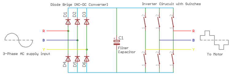
The switching or inverter section inverts the DC to AC. In this section, different types of electronic switches are used, ranging from high power transistors, IGBT or MOSFETs. The switches are rapidly turned on or off and the load receives a pulsating voltage that is very similar to AC. The output frequency is proportional to the switching rate. High switching rate provides high-frequency output whereas low switching rate provides a low-frequency output.
Different types of VFD
Depending on how VFD converts AC power to DC power and make the rectification there are other types of VFDs are available in the market.
The main three types of VFD are VSI, CSI, and PWM.
VSI type VFDs
VSI stands for Voltage-source inverter. This is the most common type of variable frequency driver. In this type of VFDs, a simple diode bridge is used to convert the AC signal into DC and a capacitor is used to store the energy. An inverter switching circuit uses the stored energy in the capacitor and provides the output.

Advantage
1.It has a good speed range.
2.Multiple motor control facility. Multiple motors can be connected with the single VSI type VFD.
3.Simple design.
4.It is cost effective from the production and installation side.
Disadvantages
1.Due to cogging effect, the load motor face jerking during start and stop situation.
2.The output provides different types of harmonics and noises.
3.If the motor speed is controlled or the speed is decreased, the overall power factor is largely get hampered which results in poor power factor.
CSI type VFDs
CSI stands for current source inverter. VSI type VFDs are designed in such a way that it could provide smooth voltage output depending on the variable frequency range but in CSI type VFDs the construction is dependable on current instead of the voltage. Also, In the case of CSI, instead of the diode bridge rectifier, SCR bridge converter is used. The output energy is filtered using series inductors as an alternative of capacitors for smooth current output. CSI type VFDs act same as like constant current generator. Instead of a square wave of voltage, CSI type VFDs is capable to provide square wave of current.

Advantage
1.Reliable then VSI type VFDs.
2.Support higher horsepower induction motors where VSI is not a suitable choice.
3.Simple design.
4.Good regeneration capabilities.
Disadvantages
1.The overall power factor is poor, especially at low RPM.
2.Cogging effect exists and could vibrate the motor shaft while running.
3.It is not suitable for multi-motor operation in respect of VSI.
PWM type VFDs
This is an improved and modified version of VSI type VFDs. PWM stands for pulse width modulation. Using the PWM technique the VFDs are capable to provide stable voltage output maintained with a frequency ratio. The construction uses a diode bridge to rectify the AC signal into a DC signal. The switching circuit controls the duty cycle in a variable frequency range. An additional regulator is used to regulate the PWM output to provide stable and proper voltage and current to the Load.
Advantage
1.No clogging or jerking effect.
2.Wide speed and control range.
3.Consist different type of protection circuits.
4.Constant power factor.
5.Induce very high efficiency.
6.Energy efficient.
Disadvantages
1.Complex to design.
2.Complex in respect of the implementation.
3.Requires additional hardware.
4.Audible noise generation in the driver circuit.
5.Costly solution.
How to select VFD for my Application?
To select the proper VFDs for a specific application, a good understanding of the load is required. Different types of motors produce different types of torque. In some applications constant torque is necessary whereas in other applications the torque needs to be controlled. Also the load across the motor is determining factor of the motor specification, mainly the Power rating.
To select the appropriate VFD for the proper application we need to evaluate or consider the following things.
1. Horsepower of the motor
2. The cost
3. The operating environment of the VFD and motors
4. Single phase or three phase
5. Single VFD with single motor or single VFD with multiple motors
6. Additional control features requirements
Advantages of VFD
There are lots of reasons why VFD is a popular choice to the consumer where other controllers are readily available. The most important reason for the popularity of VFD is the low energy consumption capabilities and initial setup cost. VFD offer high efficiency in terms of energy consumption other than any controller devices in the same segment. Due to this, in case of large factories and plants where larger horsepower motors are required, VFD offers low power consumption thus lowering the energy bill amount and provides cost-saving opportunities.
VFD limits the inrush current during the motor start and stops condition, which also decrease the inrush load in the supply line, as well as provide a safety margin for the costly motors.
Other than the above advantages VFD can lower the system maintenance cost. No additional costly electrical connection and control operations are needed. There are options to connect multiple motors that can be controlled using single VFD which in further reduce additional system setup cost.
Disadvantages of VFD
However, despite the above advantages, there are a few disadvantages also associated with the VFD system. The primary drawback of the VFD system is the initial setup investment. For a factory or a plant where multiple high horsepower motors need to be controlled using VFDs, requires high investments.
Also, VFD cause motor heating and need special motors construction. The construction needs special types of Motor insulations, as well as the motors need to be specified for inverter rated applications.
Other major disadvantage of VFD is that the main source power line is highly disturbed with distortion, line notching harmonics. Due to this, the other devices connected in the same power line also get hampered during the operating condition.
However, the advancement of the modern semiconductor industry has highly improved the construction of modern VFD systems. Before the solid state device era, rotary machines are the main component used to make the VFDs. In the modern microprocessor era, VFDs are equipped with all sorts of protections such as undervoltage, overvoltage, thermal overload protection etc. with proper control facilities. The Motor application in the industry is responsible for the 25% of the world’s electrical energy consumption, which can be efficiently controlled using VFDs.
hi sir i'm pavan kumar i had completed graduation and recently i had completed plc and scada certified course if you will give me job for me it's urgent and most important in my life.
thankyou;
Good explanation.

Nice information! The diagram you have explained above is actually great. When it is about vfd drives, it is necessary to make sure that you understand all the workings properly. The advantages and disadvantages of vfd's are explained very nicely here. Keep sharing!