

Every analog designer’s nightmare would be to deal with noise in his circuit. When it comes to switching circuits or Audio amplifiers or frequency signal circuits there is a very good chance for the circuit to be affected by noise signals. Out of the many ways to remove noise from a circuit, the most used one is called a Filter Circuit. As the name suggests, this circuit will filter out the unwanted signals (noise) from the actual signal. There are many types of filter circuit, but the most commonly used and efficient one is the Band Pass Filter which can be easily constructed using a pair of resistor and capacitors. So in this tutorial, we will learn about this Band Pass filter, the theory behind it and how it can be used in practical circuits.
What is a Bandpass filter?
A bandpass filter circuit/device is used to allow only a pre-defined set of frequencies to pass through it. It will filter of all the frequency that is below the set value and above the set value. It is a combination of a high pass filter and a low pass filter. A filter that allows only the frequencies that are higher than it is called as high pass filter and the filter that allows the frequencies that are only lower than it is called as low pass filter. A bandpass filter can be obtained by cascading both high and low pass filters. It has a huge application in audio amplifier circuits and wireless transceivers where the speaker has to play only the desired set of frequencies and ignore the rest.
There are two types of band pass filters. If the circuit involves some kind of external source of power (active devices) like transistors etc. then the circuit is called as Active bandpass filter and if the circuit does not involve any active components and consists only passive components like resistor, capacitor and inductor then the circuit is called as Passive bandpass filter. In this article we will discuss more on the passive bandpass filter. Apart from this classification, the other aspects on which the filter can be classified, will be briefed in this article.
Band Pass Filter Circuit
As told earlier we will discuss the Passive Bandpass Filter which is constructed using resistor and capacitor. It is a combination of the high pass filter and low pass filter. A sample circuit diagram of a simple passive Bandpass filter is shown below.
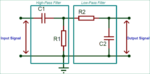
The first half of the circuit is a High-Pass filter which filters the low frequencies and allows only the frequency that is higher than the set high cut-off frequency (fcHIGH). The value of this high cut-off frequency can be calculated using the formulae
fcHIGH = 1 / 2π*R1*C1
The second half of the circuit is the Low-Pass filter circuit which filters the higher frequencies and allows only the frequency that is lower than the set low cut-off frequency (fcLOW). The value of low cut-off frequency can be calculated using the formulae
fcLOW = 1 / 2π*R2*C2
This type of filter circuit is called as 2nd order filter because it has two resistors and two capacitors. A band pass filter could be a 2nd order filter or of higher order since a minimum of two resistor and capacitor is needed for proper functioning of the circuit. Now, when an input signal frequency is supplied to this filter it outputs a frequency which is higher than fcLOW and lower than fcHIGH. In other words the output frequency can be given by fcHIGH- fcLOW, the frequency that lies in between this region is called as bandwidth. Hence the Bandwidth of the filter can be calculated by
Bandwidth = fcHIGH- fcLOW
Frequency Response of a Bandpass Filter
The Frequency response a.k.a Bode Plot curve for a 2nd order passive Bandpass filter is shown below.
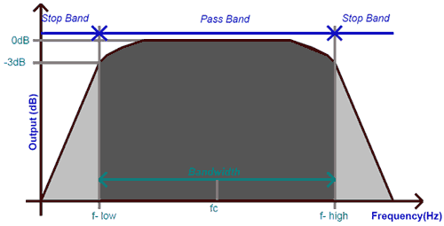
The graph is plotted against the input frequency in the X-axis and the output in decibels in the Y-axis. When the input frequency is less than the lower cut-off frequency (f-low) the output remains less than -3dB and when it exceeds that frequency, the output reaches the maximum and stays there until the frequency exceeds the higher cut-off frequency (f-high). The peak at which the output gain stays maximum is called as the resonant frequency. It is simply the geometric mean of the upper higher cut-off frequency and the lower cut-off frequency. The formulae to calculate the same is given below
Resonant frequency (Fr) =√(f – low * f - high)
The distance between the lower cut-off frequency and the higher cut-off frequency is called as bandwidth. So the input frequency will be allowed to pass through only if it is within limit of the bandwidth.
Practical Example of Band Pass filters
Let us construct a simple band pass filter to filter out a certain set of frequency and check how it actually works. The experimental set-up that I am using for this tutorial is shown below

As you can see the high pass filter is constructed using the capacitor 0.1uF (C1) and resistor 1K (R1). So the higher cut-off frequency for this circuit will be
fcHIGH = 1 / 2π*R1*C1
= 1/(2*3.17*1*10^3*0.1*10^-6)
=1577 Hz
The low pass filter is constructed using the capacitor 470pF (C2) and resistor 87K (R2). The lower cut-off frequency for this circuit can be calculated as follows
fcLOW = 1 / 2π*R2*C2
= 1/(2*3.14*8.7*10^3*470*10^-12)
=7280 Hz
From the above calculations we can infer that the circuit will allows frequencies only in the range form 1577 Hz to 7280 HZ and anything less or more than this will be filtered out by our bandpass filter. Let’s check if the same is working by building the circuit on a breadboard. My test set-up looked something like this below
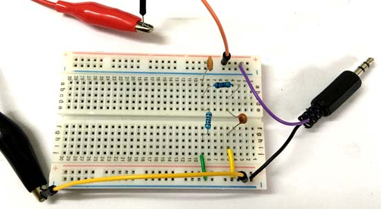
To test the circuit we need a function generator to generate signal frequency whose frequency can be controlled. Since I did not have one I decided to use my phone which has an android application that would generate the required frequencies through my 3.5mm headphone jack. This signal is then given as the input frequency to the circuit using a jack as shown above.
To check the dependency of the application I used by oscilloscope to measure the frequency of the input signal and found that the generate frequency is liable. The below picture shows the application on my phone which generates about 4,819 Hz of input frequency and the scope connected to it displays the signal and measures a frequency of 4.816 KHz which is perfect.
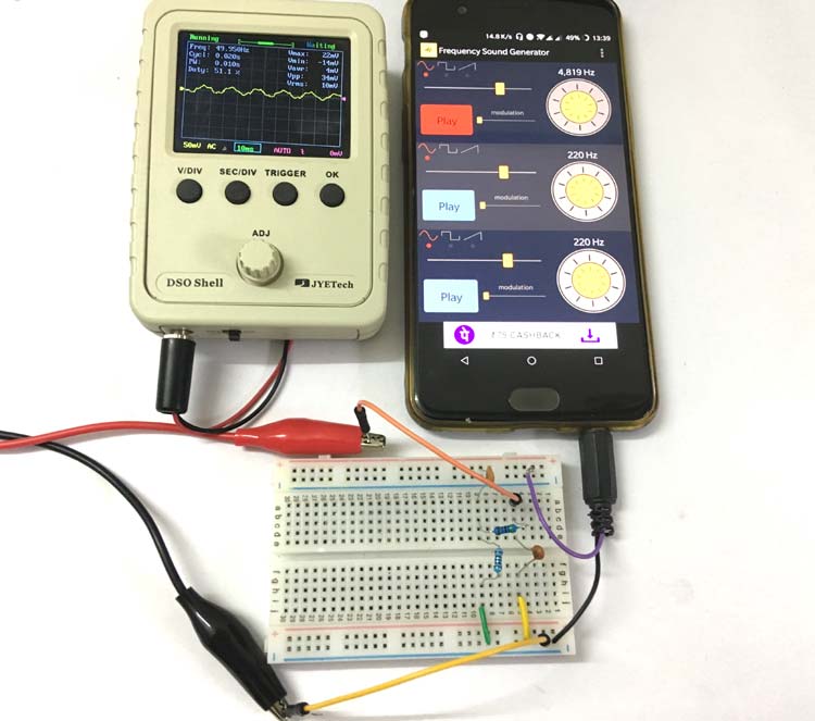
Now, we can connect the scope to the output signal of the circuit and vary the input frequency. The circuit will allow all the frequency that is in between 1500 to 7000 to be displayed on the scope and the others will be filtered out or noisy. Also keep in mind that this circuit is only for understanding purpose and hence is subjected to advancements before applying it in real terms. Also since the circuit is build over a breadboard the output signal might pick up some noise, place the capacitor as close as possible and reduce the length of its leads to reduce the problem. Hope you understood about Band Pass filters, if you have any question leave them in the comment below or use the forums.
