
A MOSFET is a type of transistor that uses an electric field to control current flow, and is widely used in switching and amplification circuits. MOSFET stands for Metal Oxide Semiconductor Field Effect Transistor, which has a gate. For simplicity, you can imagine this gate like a water tap. You rotate the tap counter-clockwise the water starts flowing out of the tap. You rotate it clockwise, and water stops flowing from the tap. Similarly, the gate voltage determines the conductivity of the device. Depending on this gate voltage, we can change the conductivity, and thus we can use it as a switch or as an amplifier, like we use a transistor as a switch or as an amplifier. Ever since the advent of the power MOSFET in the 1980s, power switching has become faster and more efficient. Almost all modern-day switching supplies use some form of power MOSFETs as their switching elements. MOSFETs are preferred for their low conduction losses, low switching losses, and as the gate of the MOSFET is made out of capacitors, it has a zero DC gate current. So, in this article, we will talk about different ways to switch on and off a MOSFET, and in the end, we will look at some practical examples that show how this affects the MOSFET.
In one of our previous articles, we discussed What is MOSFET: Its Construction, Types, and Working. You can check that out if you want to learn about the basics of a MOSFET.
Table of Contents
Fundamental Characteristics
Like a Bipolar Junction Transistor or BJT, a MOSFET is a three-terminal device, the three terminals being the GATE, the drain, and the SOURCE, with the gate controlling the conduction between the drain and source terminals.
Terminals and the Parasitic Body Diode
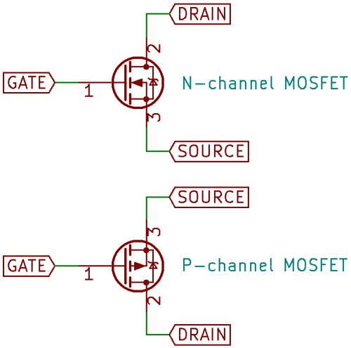
Technically speaking, a FET is inherently bidirectional, but the way power MOSFETs are constructed on the silicon level adds a parasitic anti-parallel diode across the drain and source, which makes the MOSFET conduct when the voltage across it is reversed, which is something to keep in mind. Most power MOSFET schematic symbols are drawn showing the parasitic diode.[1]
Variable Resistor Behavior
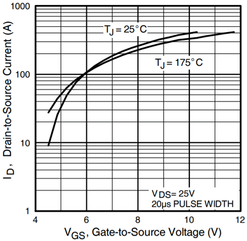
The MOSFET can be thought of as a voltage-controlled variable resistor, just like the BJT transistor can be considered a current-controlled current source. However, like the BJT, this property is not linear, that is, the resistance does not decrease linearly with applied gate voltage, as shown in the below figure from the datasheet of the popular IRF3205, while we are talking about internal resistance heat plays a key role when it comes to internal resistance.
For the most part, this does not matter, since power MOSFETs are intended to be used for switching applications, though linear use is possible. There are a few important points to consider when using a MOSFET as a switch.
Key Parameters
Drain-to-Source Breakdown Voltage and Drain Current
This depends on the application – power MOSFETs are available with breakdown ratings as low as 20V and as high as 1200V, and currents ranging from milliamps to kiloamps, a full six decades.
Gate Threshold Voltage
This is similar to the base-emitter voltage of a regular BJT, but with MOSFETs, this voltage is not as sharply defined. While a MOSFET might turn on at a relatively low voltage, it is only capable of carrying full current at a specified gate-source voltage. This is something to be careful about since most MOSFETs are specified at 10VGS. Logic-level MOSFETs are available, which specify full current at 4.5V.
Input Capacitance
Since the gate is electrically isolated from the conductive path from the drain to the source, it forms a small capacitor that has to be charged and discharged every time the MOSFET switches on and off. For power MOSFETs, this capacitance can range from hundreds of picofarads to tens of nanofarads.
N-Channel vs. P-Channel
N-channel MOSFETs turn on when the gate voltage is a few volts above the source; the rating for these voltages is mentioned in the datasheet, and the drain-source voltage is specified in positive volts. Current flows into the drain and out of the source. P-channel MOSFETs turn on when the gate is a few volts below the source, and the drain-source voltage is negative. Current flows into the source and out of the drain.
Simple MOSFET Switching Circuit
In the figure below, the simplest configuration for both the N and P-channel MOSFETs is shown.
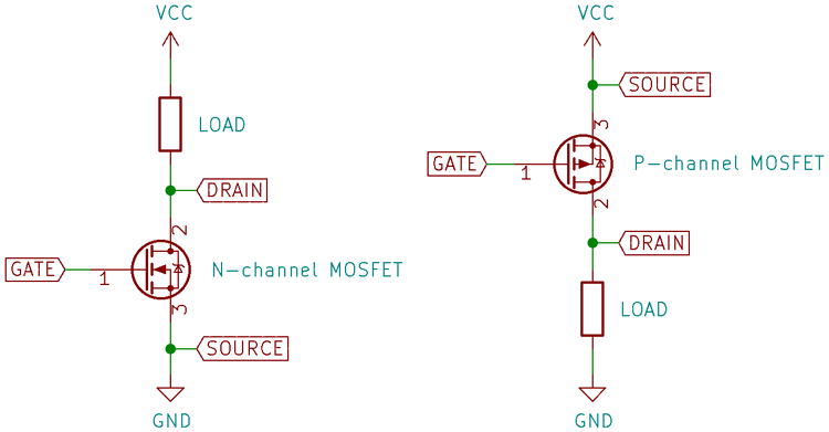
The MOSFET gates are quickly charged up from the supply voltage, turning them on. But what if the gate were left alone after turning the MOSFET on? Once the supply is removed from the gate, the MOSFET still stays on!
Why Use Gate Pull-Down/Up Resistors
Just like a regular capacitor, the gate holds its charge till it’s removed or leaks away through the very small gate leakage current. To get rid of this charge, the gate must be discharged. This can be done by connecting the gate back to the source terminal. But what if the gate is left floating by the driving circuitry? If stray charges accumulate in the gate enough to push the gate voltage beyond the threshold, then the MOSFET turns on unintentionally, which could damage circuitry further downstream. For this reason, it’s common to see a pull-down/pull-up resistor between the gate and source, which removes the charge from the gate whenever the gate voltage is removed. It is good practice to include a pull-up/pull-down resistor between the gate of a MOSFET, regardless of the kind of driver. 10K is a good value.
Gate Drive and Protection Circuit
Gate Protection with Zener Diode
The gate of a MOSFET is very sensitive since the oxide layer insulating the gate from the channel is very thin. Most power MOSFETs have a rated gate-source voltage of only ±20V! For this reason, a Zener diode across the gate is a good precaution.
Ringing and Gate Resistor
Since the gate capacitance combined with the inductance of the leads can result in ringing while switching, which is mitigated by adding a small resistor (around 10Ω) in series with the gate. The final MOSFET gate circuit looks like the figure below.

Gate Drive Requirements
The gate of a MOSFET does not normally draw any current (apart from the small leakage current), but when used in switching applications where it should be turned on and off quickly, the gate capacitance has to be charged and discharged rapidly. This takes some current, and in these cases, a gate driver is needed, which can take the form of a discrete circuit, a gate-drive IC, or a gate drive transformer.
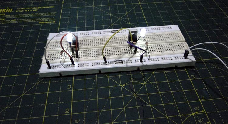
We have built a simple MOSFET as a switch circuit to show how an N-channel MOSFET (left side) and a P-channel MOSFET (right side) can be switched. You can also check out the video below that demonstrates how to turn on and turn off a MOSFET.
Substrate and Parasitic Diode
The MOSFET is a four-terminal device, with the fourth terminal being a substrate, which is the actual conductive silicon base that the rest of the transistor is made on. This terminal is usually connected to the most negative rail in the circuit (for N-channel devices, that is, and vice versa for P-channel devices) so that it does not interfere with normal operation. For power MOSFETs, it is assumed that the source is the most negative terminal (since N-channel MOSFETs are mostly used low side, switching a load to the ground), so the substrate pin is connected to the source. This creates the mentioned parasitic diode. If the substrate pin were ‘broken out’, connecting it to the most negative rail would make sure the parasitic diode would never be forward-biased in normal operation.
Frequently Asked Questions
1. Can I touch the MOSFET gate with my fingers?
For small MOSFETs, okay, no big deal. But for power MOSFETs, that gate is very sensitive. Even a tiny static shock from your hand can fry it. Better to handle it by the edges, or use an anti-static wrist strap if you have one lying around.
2. Can I leave the gate floating?
Never do that. Think of the gate like a little bucket, it holds charge. Even if your circuit is off, stray charges can sit there and turn the MOSFET on. That can make your load go crazy or even damage things. Always put a pull-down or pull-up resistor, 10k is plenty.
3. Can I drive a MOSFET directly from my Arduino?
Only if it’s a logic-level MOSFET. Normal power MOSFETs usually need around 10V at the gate to fully turn on. If you just give them 5V from Arduino, they’ll get warm and not switch properly.
4. Why does my MOSFET get hot even with a small load?
Most of the time, it’s because the gate isn’t getting enough voltage. Then the MOSFET stays in its “linear region,” acting like a resistor, and that’s where the heat comes from. Give it the proper gate voltage, and it will barely get warm.
5. Why do I need a gate resistor?
The gate is like a small capacitor. If you switch it fast, it can ring and spike, and that’s bad. A 10Ω resistor in series calms things down. Think of it as a shock absorber for your gate.
6. What about a Zener diode on the gate?
Gate oxide is thin, and most MOSFETs can only handle ±20V. Put a Zener across it, and it protects the gate from accidental over-voltage. Simple and effective.
7. What’s this parasitic diode everyone talks about?
Inside a MOSFET, there’s a built-in diode between drain and source. Most of the time you don’t have to worry, but if your load can make the voltage flip, this diode can conduct. Keep it in mind for things like motors or inductive loads.
8. Can I use a MOSFET as a variable resistor?
Yes, technically. But don’t do it for power stuff, lots of heat. MOSFETs are best used as switches, not dimmers.
9. N-channel or P-channel, which one to pick?
N-channel: Great for low-side switching (between load and ground). Fast and efficient.
P-channel: Only really useful for high-side switching. Slower and a bit more resistance, but sometimes necessary.
10. Do I always need a gate driver?
If your switching is slow and current is small, maybe not. But for anything serious, fast switching, big loads, you need a proper gate driver. Otherwise, the MOSFET switches slowly, heats up, and efficiency drops.
Related Content
Enhance your knowledge of MOSFETs and circuit design with these tutorials and guides covering practical circuits, transistor selection, and protection techniques.

Simple H-Bridge Motor Driver Circuit using MOSFET
This tutorial explains one of the most commonly used and efficient ways to drive DC motors – the H-Bridge circuit.

Difference Between MOSFET and BJT
BJTs are better suited for low-current applications, while MOSFETs excel in high-current scenarios. To select the right transistor, consider project parameters such as budget, switching speed, maximum voltage, and current ratings.

Reverse Polarity Protection Circuit
This guide shows simple methods to protect circuits from reverse polarity using a diode, diode bridge, or P-Channel MOSFET as a high-side switch.
