

Transistors are made up of semiconductor material which is most commonly used for amplification or switching purpose, although they can also be used for controlling the flow of voltage and current. Not all but most of the electronic devices contain one or more types of transistors. Some of the transistors placed individually or else generally in integrated circuits which vary according to their applications.
If we talk about amplification, the electronic current circulation can be altered by the addition of electrons and this process brings voltage variations to affect proportionally many variations in output current, bringing amplification into existence.
And, if we talk about switching, there are two types of transistors NPN and PNP. In this tutorial we will show you how to use a NPN and PNP transistor for switching, with example transistor switching circuit for both NPN and PNP type transistors.
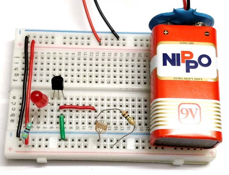
Material Required
- BC547-NPN Transistor
- BC557-PNP Transistor
- LDR
- LED
- Resistor (470 ohms, 1 mega ohms)
- Battery-9V
- Connecting wires
- Breadboard
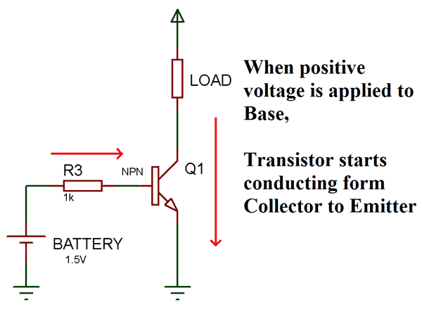
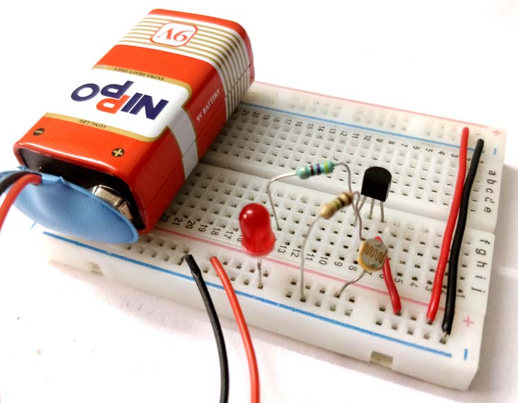
NPN Transistor Switching Circuit
Before starting with the circuit diagram, you should know the concept of NPN transistor as a switch. In an NPN transistor, Current starts flowing from collector to emitter only when a minimum voltage of 0.7V is supplied to the base terminal. When there is no voltage on Base terminal it works as an open switch between collector and emitter.
NPN Transistor Switching Circuit Diagram

Now as you see in the circuit diagram below, we made a voltage divider circuit using LDR and 1 mega ohm resistor. When there is light near the LDR, its resistances gets LOW and the input voltage at base terminal is below 0.7V which is not enough to turn ON the transistor. At this time the transistor behaves like an open switch.
When it is dark over the LDR, its resistance suddenly increases, hence the divider circuit generated enough voltage (equal or more than 0.7V) to turn ON the transistor. And hence, transistor behaves like a close switch and start flowing current between collector and emitter.
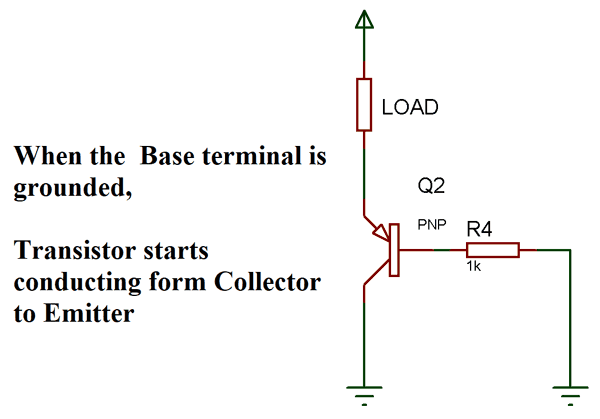
PNP Transistor Switching Circuit
The concept of PNP transistor as a switch is that, the Current stops flow from collector to emitter only when a minimum voltage of 0.7V is supplied to the base terminal. When there is no voltage on Base terminal it works as a close switch between collector and emitter. Simply, the collector and emitter are connected initially, when base voltage is provided it breaks the connection between collector and emitter.
PNP Transistor Switching Circuit Diagram
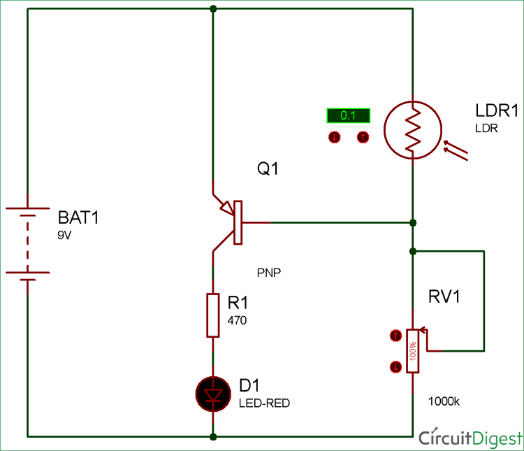
Now as you see in the circuit diagram, we made a voltage divider circuit using LDR and 1 mega ohm resistor. The working of this circuit is just opposite to the NPN transistor switching.
When there is light near the LDR, its resistance gets LOW and the input voltage at base terminal is above 0.7V which is enough to turn ON the transistor. At this time the transistor behaves like an open switch as it’s a PNP transistor.
When it is dark over the LDR, its resistance suddenly increases, hence the voltage is not enough to turn ON the transistor. And hence, transistor behaves like a close switch and start flowing current between collector and emitter.

Excellent summary of PNP NPN functions.