

Transistors are the semiconductor devices used for switching or amplifying electrical signals. They are highly durable, smaller in size and operates on a low voltage supply. A Transistor is a three terminal device:
- Base: This pin used for activating the transistor (minimum 0.7V required to turn ON a Transistor)
- Collector: Current flow through this terminal
- Emitter: Current drain out from this terminal, normally connected to ground
There are two type of transistors: NPN Transistor and PNP Transistor. In this circuit we are using a NPN transistor for amplifying the signals which are demonstrated using an oscilloscope.
As we know a transistor is generally used as a Transistor as a Switch or Transistor as an amplifier. We have explained Transistor as a Switch in our previous tutorial, now for using a transistor as an amplifier we have demonstrated the circuit and it’s working in this tutorial. For using a transistor as an amplifier we have three transistor configuration which are explained below.
What are Transistor Configurations?
Generally, there are three types of configurations and their descriptions with respect to gain is as follows:
- Common Base (CB) Configuration: It has no current gain but has voltage gain.
- Common Collector (CC) Configuration: It has current gain but no voltage gain.
- Common Emitter (CE) Configuration: It has current gain and voltage gain both.
Here, we are explaining Common-Emitter configuration, as it is the most used and popular configuration. For, learning about other two configuration, types of transistors and their working follow the linked article.
Common-Emitter Configuration
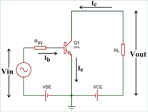
In the CE (Common-Emitter) Configuration, we get output from the collector terminal. Input is supplied to the base terminal and the emitter is common for the Input and Output. This configuration is an inverting amplifier circuit. Here, the input parameters are VBE and IB and output parameters are VCE and IC.
In this configuration, the sum of collector and base current is equal to the emitter current.
IE = IC + IB
The current gain (Beta) is defined by the ratio of collector current and base current in this configuration.
Current Gain (β) = IC / IB
This configuration is most used configuration among all the three, as it has average input and output impedance value. The output signal phase shift is 180⁰, hence the output and input are inverse to each other.
Components Required for a Transistor Amplifier Circuit
- BC547-NPN Transistor
- Resistor (10k, 4.7k, 1.5k, 1k)
- Capacitor (0.1uf, 1uf, 22uf)
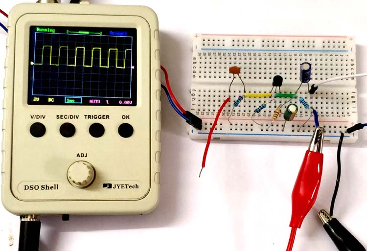
- Oscilloscope
- Connecting Wires
- Breadboard
- 12V supply
Simple Transistor Amplifier Circuit Diagram

Working of Transistor as an Amplifier
In the above circuit diagram, we have made a voltage divider circuit using resistor R1 and R2 of 4.7k and 1.5k respectively. Hence, the output of the voltage divider circuit is used for proper biasing to turn ON the transistor. A transistor’s base terminal voltage required to turn ON the transistor ranges from 0.7 (min) to 5V (max). You can change the resistor value but the base input voltage should not exceed the range. When supply is given to the circuit, the voltage divider circuit output provide enough voltage to bias the transistor.
Here, R4 is used as current limiting resistor and C2 is used as bypass capacitor and R3-C3 are making a RC filter for the output signal.
There are three operating regions of a transistor mentioned below:
- Cut-off region: when voltage between base and emitter is less than 0.7V, transistor is in cut-off region.
- Saturation region: When VBC and VBE increases and both get forward biased, then the transistor is in saturation region.
- Active region: when base voltage increases, but VBC (base to collector) voltage is still negative, upto this value, transistor remain in active region.
A transistor will work as an amplifier only when it is operated in active region. Here, the transistor work as an amplifier, we have used common-emitter configuration.
Hence, the pulse input supplied to base get amplified and received at capacitor C3.
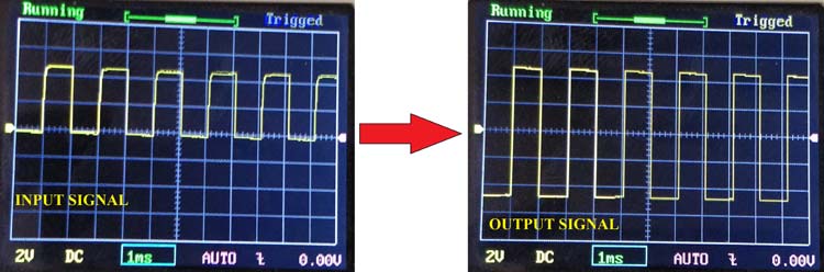
Now, the question is how it gets amplified? When the input pulse goes HIGH it turn on the transistor and current start flowing from collector to emitter for that time, which means the pulse from collector to emitter also gets HIGH for that time and vice versa. So, the transistor is just mimicking the input pulse (which is off low voltage) to the output pulse (which is off HIGH voltage, 12V in our circuit).
