

A square wave to Sine wave converter circuit is an important analog circuit that converts square waveforms to sine waveforms. It has a broad spectrum of applications in many different areas of electronics, such as mathematical operations, acoustics, audio applications, inverters, power sources, function generators, etc.
In this project, we will discuss how a square wave to sine wave converter circuit works and how it can be built using simple passive electronics. You can also check out other waveform generator circuits listed below.
This complete guide introduces you to building the square wave to sine wave converter circuit diagram using only passive components. Our square wave to sine wave converter diagram gives us a good example of what can be done with RC networks, which can be attempted by any electronics lover.
- Square Wave Generator Circuit
- Sine Wave Generator Circuit
- Triangle Wave Generator Circuit
- Sawtooth Wave Generator Circuit
Table of Contents
- Square to Sine Wave Converter using RC Network
- Complete Component Selection Table for Different Frequencies
- Square to Sine Wave Converter Circuit Diagram
- Working Principle of Square Wave Converter
- How to Select R and C Values for Square Wave Converter
- Testing our Square to Sine Wave Converter Circuit
- Frequently Asked Questions
- Related Circuit Projects
Square to Sine Wave Converter using RC Network
A square wave to sine wave converter can be built using 6 passive components, namely capacitors and three resistors. Using these three capacitors and three resistors, a 3-stage RC network can be built that takes a square wave as an input and a sine wave as an output. A simple single-stage RC network circuit is shown below.
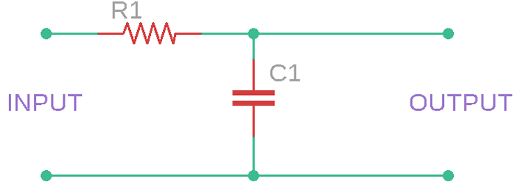
In the above circuit, a single-stage RC filter is shown where a single resistor and a single capacitor are used. The above circuit is pretty simple. The capacitor gets charged depending on the status of the square wave. If the square wave in the input is in a high position, the capacitor will get charged, and if the square wave is in a low position, the capacitor gets discharged.
The best way to convert a square wave to a sine wave is through a multi-stage RC (resistor-capacitor) network. The design for the square wave to sine wave converter requires only six passive components, three capacitors and three resistors, in a cascaded configuration.
A varying signal wave, such as a square wave, has a frequency; depending on this frequency, the output of the circuits changes. Due to this behaviour of the circuit, the RC filter is called an RC integrator circuit. An RC integrator circuit changes the signal output depending on the frequency and could change the square wave to a triangular wave or a triangular wave to a sine wave.
Complete Component Selection Table for Different Frequencies
Frequency Range | Resistor Value (All Stages) | Capacitor Value (All Stages) | Time Constant (τ) | Sine Wave Purity | Amplitude Reduction | Applications |
|---|---|---|---|---|---|---|
| 100Hz - 1kHz | 100kΩ | 1μF | 100ms | 95% | 60% | Audio processing, low-frequency signals |
| 1kHz - 5kHz | 10kΩ | 100nF | 1ms | 94% | 55% | Audio equipment, function generators |
| 5kHz - 10kHz | 10kΩ | 10nF | 100μs | 93% | 50% | Audio circuits, signal processing |
| 10kHz - 20kHz | 5kΩ | 10nF | 50μs | 92% | 50% | High-quality audio, instrumentation |
| 20kHz - 40kHz | 1kΩ | 4.7nF | 4.7μs | 90% | 50% | Function generators, test equipment |
| 40kHz - 80kHz | 1kΩ | 2.2nF | 2.2μs | 88% | 45% | Switching power supplies |
| 80kHz - 100kHz | 470Ω | 2.2nF | 1μs | 85% | 45% | High-frequency applications |
| 100kHz - 200kHz | 470Ω | 1nF | 470ns | 82% | 40% | RF signal conditioning |
Square to Sine Wave Converter Circuit Diagram
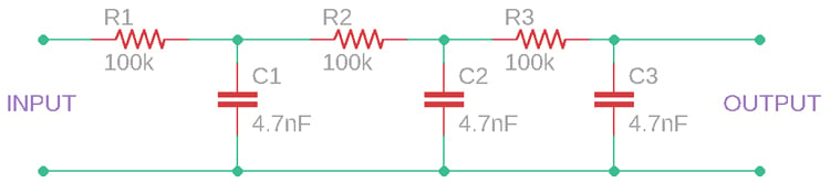
In this tutorial, we are using these RC integrator circuits (RC filter networks) to convert a square wave to a sine wave. The complete converter circuit diagram is given below, and as you can see, it has only very few passive components. The square wave to sine wave converter circuit diagram is based on a basic RC integrator circuit. The integrated circuit functions on the basis that capacitors charge and discharge at different rates depending on frequency.

The circuit consists of three stages of RC filter circuits. Each stage has its own conversion significance. Let's understand the working of each stage and how it contributes to converting a square wave to a sine wave by looking at the waveform simulation
Working Principle of Square Wave Converter
In this square wave to sine wave converter diagram, there are cascaded RC stages for converting the input square wave into an output sinusoidal wave through the use of exponential, triangle, and sine conversions. To know how the square wave to sine wave converter works, one needs to understand what is happening in each RC filter stage. Proper selection and placement of the components is essential for the optimal performance of your square to sine wave converter. The circuit uses the same component values in all three stages to ensure a balanced conversion. Our square wave to sine wave converter diagram showcases a three-stage design where each stage performs a specific wave transformation: Understanding how to convert square wave to sine wave requires analysing each conversion stage in detail.
First Stage: Square to Exponential Wave Conversion
The initial RC network in our square wave to sine wave converter creates an exponential waveform from the input square wave. In the first RC network stage, it has a resistor in series and a capacitor in parallel. The output is available across the capacitor. The capacitor gets charged up via the resistor in series. But, as the capacitor is a frequency-dependent component, it takes time to charge. However, this charge rate can be determined by the RC time constant of the filter. By the charging and discharging of the capacitor, and since the output comes from the capacitor, the waveform is highly dependent on the capacitor charge voltage. The Capacitor voltage during the charge time can be determined by the following formula-
VC = V (1 – e-(t/RC))And discharge voltage can be determined by–
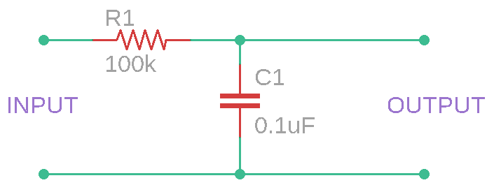
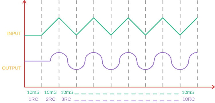
VC = V (e-(t/RC))Therefore, from the above two formulas, the RC time constant is an important factor to determine how much charge the capacitor stores, as well as how much discharging is done for the capacitor during an RC time constant. If we select the value of the capacitor as 0.1uF and the resistor as 100 k-ohms, like the image below, it will have a time constant of 10 milliseconds. The RC time constant is significant in the square wave to sine wave converter circuit diagram, as it affects how the square wave to sine wave conversion is initially accomplished, as the exponential charging curve is the first step in smoothing the wave.
Now, if a 10ms constant square wave is provided across this RC filter, the output waveform will be like this due to the charging and discharging of the capacitor in the RC time constant of 10ms.
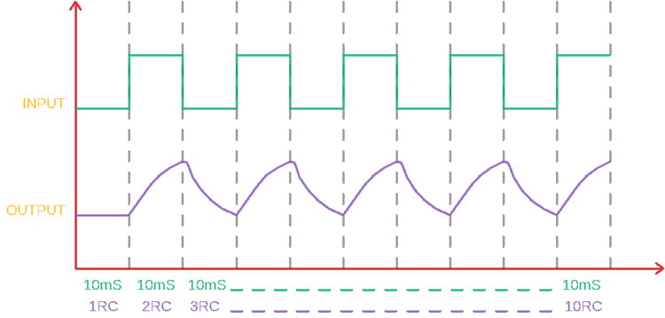
The wave is a parabolic-shaped exponential waveform.
Second Stage: Exponential to Triangular Wave
Now the output of the first RC network stage is the input of the second RC network stage. This RC network takes the parabolic-shaped exponential waveform and makes it a triangular waveform. By using the same RC constant charging and discharging scenario, the second stage RC filters provide a straight ascending slope when the capacitor gets charged and a straight descending slope when the capacitor gets discharged. The second RC stage of our square wave to sine wave converter allows us to keep integrating to convert the exponential curve to a triangular waveform.
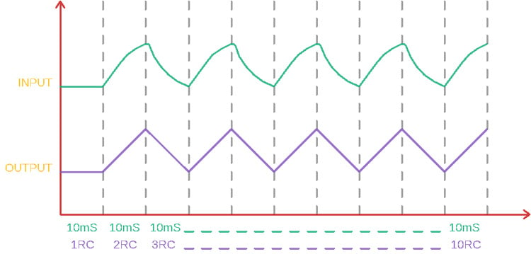
The output of this stage is ramp output, a proper triangular wave. This stage shows how RC integration is smoothing the waveform as we would finally complete our convert square wave to sine wave function more closely to the sine wave output
Third Stage: Triangle to Sine Wave Conversion
In this third RC network stage, the output of the second RC network is the input of the third RC network stage. It takes the triangular ramp wave as an input and then changes the shapes of the triangular waves. It provides a sine wave where the upper and lower portions of the triangular wave smoothen out, making them curved. The output is pretty close to a sine wave.
How to Select R and C Values for Square Wave Converter
Proper component selection is crucial for an effective square wave to sine wave converter. The capacitor and resistor values are the most important parameters of this circuit. Because, without the proper capacitor and resistor value, the RC time constant will not be matched for a particular frequency, and the capacitor will not get enough time to charge or discharge. This results in a distorted output, or even at high frequency, the resistor will work as the only resistor and could produce the same waveform as it was given across the input. So, capacitor and resistor values must be chosen properly.
For our square wave to sine wave converter circuit diagram, utilising 4.7nF capacitors and 1kΩ resistors, the best frequency response is centred on 33kHz.
If the input frequency can be changed, then one can choose a random capacitor and resistor value and change the frequency according to the combination. It is good to use the same capacitor and resistor value for all filter stages.
For a quick reference, at low frequencies, use a higher value capacitor, and for high frequencies, choose a lower value capacitor. However, if all the components, R1, R2, and R3 are the same value and all capacitors C1, C2, and C3 are the same value, the capacitor and resistor can be selected using the below formula–
f = 1/(2π x R x C)Where F is the frequency, R is the resistance value in Ohms, and C is the capacitance in Farad.
The schematic below is a three-stage RC integrator circuit that was described previously. However, the circuit uses 4.7nF capacitors and 1 kilo-ohm resistors. This creates an acceptable Frequency range in the 33 kHz range.
Testing our Square to Sine Wave Converter Circuit
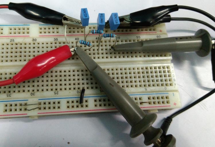
The schematic is made in a breadboard, and a function generator, along with an oscilloscope, is used to check the output wave. If you do not have a Function generator to generate the square wave, you can either build your own square wave generator or even an Arduino Waveform Generator, which you can use for all waveform-related projects. The circuit is very simple, and hence it is easily built on the breadboard, as you can see below.
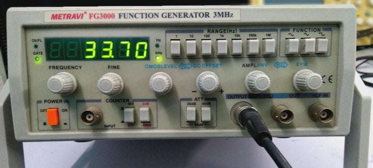
For this demonstration, we are using a function generator, and as you can see in the image below, the function generator is set to the desired 33 kHz square wave output. Adjust your function generator to output a 33kHz square wave equal to the design frequency of your square wave to sine wave converter circuit diagram.
The circuit works across a 20-40kHz frequency range, demonstrating flexibility in the square wave to sine wave converter design.
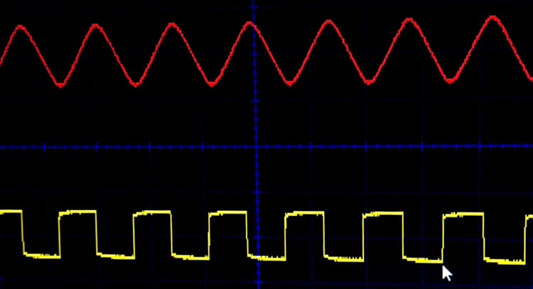
The output can be observed on an oscilloscope; a snapshot of the output from the scope is given below. The input square wave is shown in yellow colour, and the output sine wave is shown in red colour.
Frequently Asked Questions on the square wave to sine wave converter
⇥ 1. What is a square wave to sine wave converter?
A square wave to sine wave converter is an electronic circuit that converts square wave digital signals into clean, smooth sine wave outputs by using passive components (e.g. resistors and capacitors) in RC filter networks.
⇥ 2. How does the RC network convert a square wave to a sine wave?
RC networks take advantage of the charging and discharging characteristics of the capacitors to gradually smooth the square wave edges. The RC networks are waveform integrators. As you add networks: square → exponential → triangular → sine wave is generated (and you control the time constants).
⇥ 3. What components are required to make the square wave to sine wave processor?
You will require 3 resistors, 3 capacitors, and a breadboard. Please note that typical component values are 1kΩ resistors and 4.7nF capacitors if operating at 33kHz. You will not be using any active components and will not require a power supply for a basic square wave to sine wave conversion.
⇥ 4. Why do we use 3 stages in a square wave to sine wave converter?
3 stages of signal processing are what we recommend so that you can get the best shape for your wave: the first stage produces exponential curves, the second stage produces triangular waves, and the third stage outputs a wave that looks similar to a sine wave. More stages will clean up the sine wave, but the amplitude will come down.
⇥ 5. How do I find RC values for desired frequencies?
Use f = 1/(2π × R × C). For example, if you want 33kHz with 1kΩ resistors, you will need 4.7nF capacitors. Keep the same RC values in all of the stages to maintain phase response.
⇥ 6. What frequency range for best results for RC sine (sine to RC)?
RC converters work best for frequencies between 10Hz to 100kHz. At lower frequencies, you will need larger capacitors, and at higher frequencies, you will require lower values. The best sine wave approximation is in the 20-40kHz range when using standard components.
The circuit worked as expected for an input frequency ranging from 20kHz to 40kHz. You can refer to the video below for more details on how the circuit works. Hope you enjoyed the tutorial and learned something useful. If you have any questions, leave them in the comment section below. Or you can also use our forum to post other technical questions.
Related Circuit Projects
Advance your skills with hands-on circuit projects that explore waveform generation and signal processing. From converting square waves to sine waves, designing precise band-pass filters, and building RC phase-shift oscillators, to generating custom waveforms with Arduino, these projects give you practical experience in both analog and microcontroller-based circuits.

Simple Square Wave to Sine Wave Converter
In this project, we will discuss how a square wave to sine wave converter circuit works and how it can be built using simple passive electronics.

There are many types of filter circuit but the most commonly used and efficient one is the Band Pass Filter So in this tutorial we will learn about Band Pass filter, the theory behind it and how it can be used in practical circuits.

RC Phase Shift Oscillator using Op-Amp
A Phase Shift Oscillator is an electronic oscillator circuit which produces sine wave output. It can either be designed by using transistor or by using an Op-amp as inverting amplifier.
Comments
How should the R and C values ideally relate to the load resistance?
Thank-you,
Thank you for this very interesting information. I would like to make a square to sine wave converter for the output of my household Trace 2012 Inverter. I’m not sure where to get the capacitors and resistors that I would need nor is it obvious what sizes they should be. It’s a 60Hz, 120 VAC, 2000 Watt (steady state) output device. One frustration I had with the tutorial was trying to reconcile the 100K (Ohms) labeling on the final 3 stage circuit diagram. The text describing this circuit has the correct value which is 1K (1 kilo-ohms). I was so focused on using the diagram for understanding that it took me a very long time to realize the diagram resistor labelings were incorrect.

Good article. Thanks Circuit Digest.