

In this tutorial we are going to show you that how to Generate a Low Power Square Wave Using IC 4047, we will also confirm the output using Oscilloscope. In the Astable mode the output waveform of 4047 IC fluctuates between high and low logic levels which is identical to the square wave. It only requires few resistors and capacitors to add externally to generate the square wave. This can be used as a clock pulse for some of the ICs which need clock pulse to operate. This Square wave can be further converted into Sine wave by adding few more resistors and capacitors.
Material Required
- IC 4047
- Oscilloscope
- Potentiometer value (1M ohms)
- Resistor value (1k and 200 ohm)
- Capacitor value (0.001uf and 0.1uf)
- Connecting wires and probes
- 12v supply
Circuit Diagram

The circuit is for this Square wave generator is given above. You can vary the frequency of square wave by moving the potentiometer or you can use different value of resistor and capacitor to vary the output frequency.
Note: Minimum Value of R: 10 Kilo Ω
Maximum Value of R: 1 Mega Ω
Minimum Value of C for Astable Mode: 100 pF
Minimum Value of C for Monostable Mode: 1000 pF
Before going into detail we should know about IC 4047.
IC 4047
The 4047 IC is one of the popular IC with low power consumption. It provides both Monostable (one-shot) and Astable (free running) operation. It has a wide range of input voltage (3v to 18v) and DC current input is up to ±10mA with a high operating temperature range of −55°C to +125°C. Here, we are using the IC to generate square and sine wave, for this we just need few resistor and capacitor. You can use the IC for generating clock pulse for various applications. This IC is mainly used in Inverter circuit to generate Alternating current from DC current.
Application of this IC are Frequency discriminators, Timing circuits, Time-delay applications, Envelope detection, Frequency multiplication, and Frequency division.
Pin Diagram IC 4047
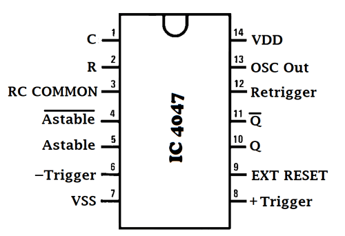
Pin configuration IC 4047
|
Pin No. |
Pin Name |
Description |
|
1 |
C |
Used to connect external capacitor |
|
2 |
R |
Used to connect external resistor |
|
3 |
RCC |
Common pin for connecting resistor and capacitor to it |
|
4 |
AST’(Astable bar) |
Low when used in Astable mode |
|
5 |
AST |
High when used in Astable mode |
|
6 |
-Trigger |
When used in Monostable mode we give High to Low transition to this pin |
|
7 |
Vss |
Ground pin of IC |
|
8 |
+Trigger |
When used in Monostable mode we give Low to High transition to this pin |
|
9 |
EXT RESET |
It’s an external reset pin. By giving a high pulse to this pin, it resets the output Q to low and Q’ to high |
|
10 |
Q |
Give normal high output |
|
11 |
Q’ |
Inverse output of pin 10, means it gives low output |
|
12 |
Retrigger |
Used in Monostable mode to simultaneously retrigger +trigger and –trigger pin |
|
13 |
OSC Out |
Gives oscillated output |
|
14 |
Vdd |
Positive input pin of IC |
Working of the Circuit for Generating Square Wave
We can supply an input voltage range of 3v to 15v to the IC. In our circuit, we are giving 12v. A resistor and capacitor is externally connected to the PIN 2 and made short with PIN 3. The combination of resistor and capacitor (RC) generates output with a certain frequency. The output for the square wave is taken from the PIN 10 in series with a 200 ohm resistor.
The formula for finding the value of frequency of Square Wave is given below:
f = 1 / 8.8RC
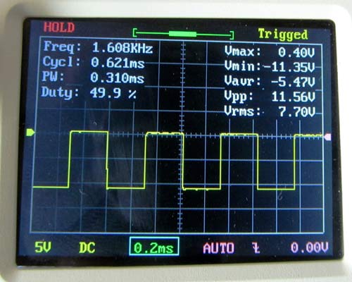
Example: for calculating frequency mathematically for the waveform shown in figure
Here, the potentiometer is at approx. 7-8% and the value of C is 0.001uf.
So, the frequency is: f = 1 / 8.8*70,000*0.001*10-6
f = 1623.37 or 1.6Khz (approx.)
The same formula can be used to find the value of RC if frequency is known.
The disadvantage of 4047 IC is that, we cannot adjust the duty cycle and the output of this IC has the constant duty cycle of 50%. And for controlling the frequency we use to vary the values of R and C in the circuit.
The square wave generated by this circuit can be easily converted into Sine wave using few resistors and capacitors.
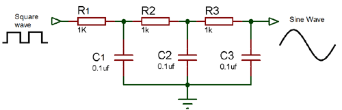
Square to Sine Wave Converter

This Circuit is the modification of the above circuit for getting the Sine wave from square wave. For converting the square wave into sine wave we need to add few resistors and capacitors as shown in the circuit diagram below:

By making this small modification we are able to convert the square wave into a sinusoidal wave.

Nice information .thank you.