

A zero-crossing detector circuit is a useful application of an op-amp as a comparator. This electronic circuit precisely identifies when an AC waveform transitions through zero voltage, tracking the changes in the sine waveform from positive to negative or vice versa while it crosses zero voltage. It can also be used as a square wave generator. They have many applications, like a time marker generator, phase meter, and frequency counter. A zero-crossing detector can be designed using various methods, including transistors, operational amplifiers, or optocoupler ICs. In this article, we will use an op-amp to build a zero-crossing detector circuit, and as mentioned previously, the op-amp will work as a comparator here.
Table of Contents
Working & Output Waveform
A zero-crossing detector works by comparing an AC input signal to a reference voltage, usually ground. Its ideal output waveform is shown below:
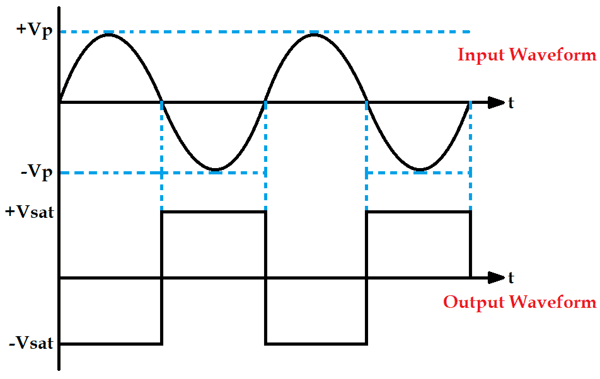
It can be seen in the above waveform that whenever the sine wave crosses zero, the output of the op-amp will shift either from negative to positive or from positive to negative. It shifts from negative to positive when the sine wave crosses from positive to negative and vice versa. This is how a zero-crossing detector detects when the waveform crosses zero every time. As you can observe that the output waveform is a square wave, so a zero-crossing detector is also called a square wave generator circuit.
Key Characteristics
| Parameter | Description | Typical Value |
| Input Signal | AC Sine Wave | 12V RMS |
| Output Signal | Square Wave | ±9V |
| Detection Points | Zero-Crossing Instances | 0°, 180°, 360° |
| Response Time | Switching Speed | <1μs |
Zero-Crossing Detector Circuit Using Op-Amp
Materials Required
- Op-amp IC (LM741)
- Transformer (230V-to-12V)
- 9V supply
- Resistor (10k – 3nos)
- Breadboard
- Connecting Wires
- Oscilloscope
Circuit Diagram and Wiring

In this zero-crossing detector using an op-amp configuration, the 230V AC supply is connected to a 12-0-12V transformer. The phase output connects to pin 2 (inverting input) of the LM741 op-amp, while the neutral connects to the circuit ground. The positive terminal of the 9V battery connects to pin 7 (Vcc) of the op-amp.

Circuit Operation
In a zero-crossing detector circuit, the non-inverting terminal of the op-amp is connected to the ground as a reference voltage, and a sine wave input (Vin) is fed to the inverting terminal of the op-amp, as you can see in the circuit diagram. This input voltage is then compared with the reference voltage. Any general-purpose op-amp IC can be used here; we have used the op-amp IC LM741, which provides reliable zero-crossing detection performance.
- Positive Half Cycle: When input voltage > 0V, inverting input > non-inverting input → Output = Negative Saturation (-9V)
- Negative Half Cycle: When input voltage < 0V, inverting input < non-inverting input → Output = Positive Saturation (+9V)
- Zero-Crossing: Instantaneous switching between positive and negative output states
Now, when you consider the positive half cycle of the sine wave input. We know that, when the voltage at the non-inverting end is less than the voltage at the inverting end, the output of the Op-amp is Low or of negative saturation. Hence, we will receive a negative voltage waveform.
Then in the negative half cycle of the sine wave, the voltage at the non-inverting end (reference voltage) becomes greater than the voltage at the inverting end (input voltage), so the output of the Op-amp becomes High or of positive saturation. Hence, we will receive a positive voltage waveform, as you can see in the image below:
Thus, it is clear that this circuit can detect the zero-crossing of a waveform by switching its output from negative to positive or from positive to negative at precisely the moment when the input signal crosses zero voltage.
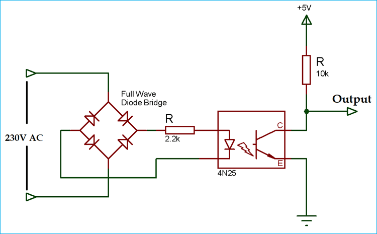
Zero-Crossing Detector Circuit Using Optocoupler
As we have already mentioned, there are many ways to design a zero-crossing detector. Here, we present an alternative zero-crossing detector circuit using an optocoupler for enhanced isolation and safety. By observing the output waveform, you can see that the output changes state whenever the input AC waveform crosses zero.
Below is the output waveform of the zero-crossing detector circuit using an optocoupler:
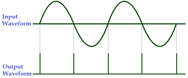
The zero-crossing pulse output is getting HIGH at 0⁰, 180⁰, and 360⁰, or we can say after every 180⁰.
Op-Amp vs Optocoupler
The table below highlights the key differences between op-amp and optocoupler-based zero-crossing detectors.
| Feature | Op-Amp Method | Optocoupler Method |
| Output Type | Continuous Square Wave | Pulse at Zero-Crossing |
| Isolation | No Electrical Isolation | Complete Electrical Isolation |
| Circuit Complexity | Simple | Moderate |
| Safety | Requires Careful Design | Inherently Safe |
| Cost | Lower | Slightly Higher |
FAQ
What does a zero-crossing detector actually do?
It just spots the moment an AC signal passes through zero volts. That’s handy for timing, frequency measurement, or cleanly switching AC loads.
Why build it with an op-amp?
Because it’s simple and cheap. Perfect if you’re learning or working with low voltages.
So why bother with an optocoupler?
Mainly for safety. The optocoupler keeps your high-voltage side and low-voltage side isolated, which makes the whole thing safer to use.
Why does the op-amp version give a square wave?
Every time the input crosses zero, the op-amp output flips hard between positive and negative. That sharp switching shows up as a square wave.
Do I have to use an op-amp or optocoupler?
Not really. People also build these with transistors, but op-amps and optos are more common.
Does this only work with sine waves?
Nope. Any AC waveform crosses zero. If the shape is messy, though, the output won’t be as clean.
Can I hook this straight to mains?
Don’t, unless you’ve got isolation in place. That’s exactly where the optocoupler approach shines.
More Op-Amp Based Circuits
Enhance your circuit knowledge with additional op-amp designs that demonstrate their versatility in real-world applications.

Overcurrent Protection using Operational Amplifier
This circuit uses an op-amp to sense excess current and provide protection, helping prevent damage to connected electronic components.

Designing a Schmitt Trigger using Op-Amp
This project explains the operation of Schmitt triggers and shows how to design a fast and reliable Schmitt trigger circuit using an op-amp.

Op-amp based Peak Detector Circuit
This peak detector circuit uses an op-amp to overcome diode voltage drop, allowing accurate detection of input signal peaks.
Comments
Then Use 220k Resistor it will work properly even you can use the PZ817 too in this circuit,
I have experience using this, I already design the low cost, Small Size, safe, power efficient VFD using this type of ZCD Circuit for very small Application,.
And now I am upgrading with Op-Amp with both Phase side and Neutral Side.

Hello Pankaj,
In the 2nd sample circuit, Zero Crossing Detector Using Optocoupler, is there supposed to be a transformer between the 230VAC input and the Bridge Rectifier? Not sure is possible to apply 230V to the 4N25 with only a 2.2k resistor.
Thank you!
Agustin