In the previous article, we discussed the basics of impedance matching and how to use an impedance matching transformer. Apart from using an impedance matching transformer, designers can also use Impedance Filter circuits at the output of an RF amplifier which can double up as a filtering circuit and also as an impedance matching circuit. There are many types of filter circuits that can be used in for Impedance matching, the most common ones are discussed in this article.
LC Filter Matching
Various LC filters can be used to match impedances and provide filtering. Filtering is especially important on the output of power RF amplifiers because they generate a lot of unwanted harmonics that have to be filtered before they are transmitted by the antenna because they can cause interference and transmitting on frequencies other than the ones the station is approved to transmit on can be illegal. We will cover low-pass LC filters because radio power amplifiers only generate harmonics, and harmonic signals are always the whole multiple of the base signals, so they always have higher frequencies than the base signal – this is why we use low-pass filters, they let the wanted signal through while getting rid of harmonics. When designing LC filters, we will talk about source resistance and load resistance instead of impedance, because if the load or source has some series or parallel inductance or capacitance, and therefore non-resistive impedance the calculations get much more complex. In this case, it is best to use a PI filter or L filter calculator. In most cases, such as integrated circuits, properly made and tuned antennas, TV and radio receivers, transmitters, etc. output/input impedance = resistance.
“Q” factor
Every LC filter has a parameter known as a Q (quality) factor, in the low pass and high pass filters it determines the steepness of the frequency response. A low Q filter will be very broadband and will not filter out undesired frequencies as good as a high Q filter. A high Q filter will filter out undesired frequencies, but it will have a resonant peak, so it will also act as a bandpass filter. A High Q factor sometimes reduces efficiency.
L filters
L filters are the simplest form of LC filters. They consist of a capacitor and an inductor, connected in a way similar to that found in RC filters, with the inductor replacing the resistor. They can be used to match impedance that is higher or lower than the source impedance. In every L filter, there is only one combination of L and C that can match a given input impedance to given output impedance.
For example, to match a 50 Ω load to a 100 Ω load at 14MHz, we need a 560nH inductor with a 114pF capacitor – this is the only combination that can do matching at this frequency with these resistances. Their Q factor, and therefore how good the filter is equal to
√((RA/RB)-1)=Q
Where RA is the bigger impedance, RL is the smaller impedance, and Q is the Q factor with the appropriate load connected.
In our case, the loaded Q will be equal to √((100/50)-1) = √(2-1) = √1 = 1. If we wanted more or less filtering (different Q), we would need the PI filter, where Q is fully adjustable and you can have different L and C combinations that can give you the required matching at a given frequency, each with a different Q.

To calculate the values of L filter components, we need three things: output resistance of the source, resistance of the load, and the frequency of operation.
For example, the output resistance of the source will be 3000 Ω, load resistance will be 50 Ω, and the frequency is 14 MHz. Since our source resistance is larger than the load resistance, we will use the “b” filter
First, we need to calculate the reactance’s of the two components of an L filter, then we can calculate the inductance and capacitance based on reactance and frequency of use:
XL=√(RS*(RL-RS))
XL=√(50 Ω*(3000 Ω-50 Ω)
XL=√(50 Ω*(3000 Ω-50 Ω)
XL=√(50 Ω*2950 Ω)
XL=√(50 Ω*2950 Ω)
XL=√147500 Ω2
XL=384.1 Ω
We use a reactance calculator to determine an inductance that has a 384.1 Ω reactance at 14MHz
L=4.37 μH
XC=(RS*RL)/XL
XC=(50 Ω*3000 Ω)/384.1 Ω
XC=150000 Ω2/384.1 Ω
XC=390.6 Ω
We use a reactance calculator to determine an inductance that has a 390.6 Ω reactance at 14MHz
C= 29.1 pF


As you can see, the filter’s frequency response is a low pass with a resonant peak at 14MHz, the resonant peak is caused by the filter having a high Q if the Q was lower, the filter would be lowpass without a peak. If we wanted a different Q, so the filter would be more broadband, we would need to use a PI filter because the L filter’s Q depends on source resistance and load resistance. If we use this circuit to match the output impedance of a tube or a transistor, we would need to subtract the output to ground capacitance from the filter’s capacitor because they are in parallel. If we use a transistor with a collector-emitter capacitance (aka output capacitance) of 10pF, the capacitance of C should be 19.1 pF instead of 29.1 pF.
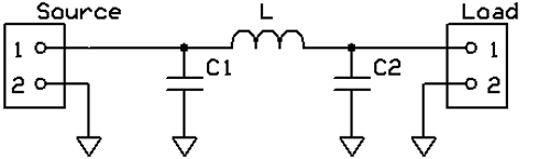
PI Filters
The PI filter is a very versatile matching circuit, it consists of 3 reactive elements, usually two capacitors and one inductor. Unlike the L filter, where only one combination of L and C gave the required impedance matching at a given frequency the PI filter allows for multiple combinations of C1, C2, and L to achieve the desired impedance matching, each combination having a different Q.
PI filters are more often used in applications, where there is need for tuning to different load resistances or even complex impedances, such as RF power amplifiers because their input to output impedance ratio (ri) is determined by the ratio of capacitors squared, so when tuning to a different impedance the coil can stay the same, while only capacitors are tuned. C1 and C2 in RF power amplifiers are often variable.
(C1/C2)²=ri
When we want a more broadband filter we use Q a little bit above Qcrit when we want a sharper filter, such as at the output of an RF power amplifier we use Q that is much bigger than Qcrit, but below 10, as the higher the filter’s Q the lower the efficiency. Typical Q of PI filters in RF output stages is 7, but this value can vary.
Qcrit=√(RA/RB-1)
Where: RA is the higher of the two (source or load) resistances and RB is the smaller resistance. In general, the PI filter at higher Q can be regarded, ignoring impedance matching as a parallel resonant circuit made from a coil L and a capacitor C with a capacitance equal to:
C=(C1*C2)/(C1+C2)
This resonant circuit should resonate at the frequency the filter will be used.
To calculate the values of a PI filter components we need four things: output resistance of the source, resistance of the load, the frequency of operation, and Q.
For example, we need to match an 8Ω source to a 75Ω load with a Q of 7.
RA is the higher of the two (source or load) resistances and RB is the smaller resistance.
XC1=RA/Q
XC1=75 Ω/7
XC1=10.7 Ω
We use a reactance calculator to determine a capacitance that has a 10.7 Ω reactance at 7 MHz
C1=2.12 nF
XL=(Q*RA+(RA*RB/XC2))/(Q2+1)
XL=(7*75 Ω+(75 Ω*8 Ω/3.59 Ω))/72+1
XL=(575 Ω+(600 Ω2/3.59 Ω))/50
XL=(575 Ω+(167 Ω))/50
XL=742 Ω/50
XL=14.84 Ω
We use a reactance calculator to determine an inductance that has a 14.84 Ω reactance at 7 MHz
L=340 nH
XC2=RB*√((RA/RB)/(Q2+1-(RA/RB)))
XC2=8 Ω*√((75 Ω/8 Ω)/(Q2+1-(75 Ω/8 Ω)))
XC2=8 Ω*√(9.38/(49+1-3.38))
XC2=8 Ω*√(9.38/46.62)
XC2=8 Ω*√0.2
XC2=8 Ω*0.45
XC2=3.59 Ω
We use a reactance calculator to determine a capacitance that has a 3.59 Ω reactance at 7 MHz
C2=6.3nF


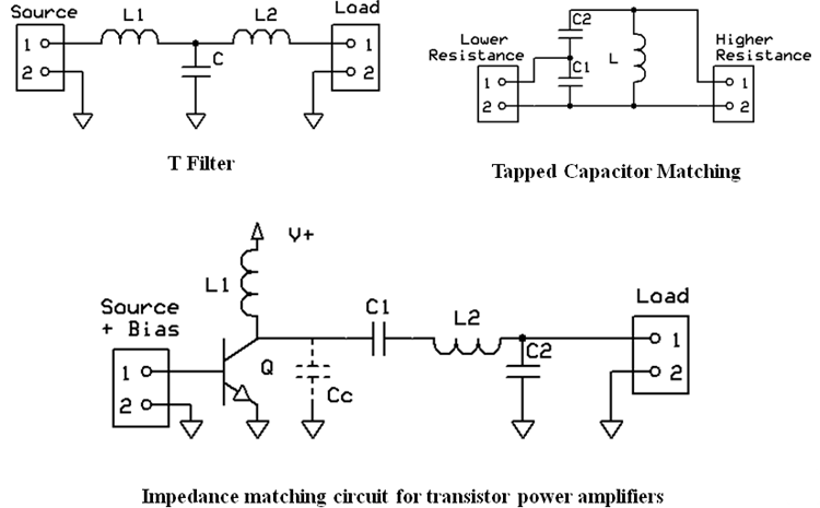
Like with the L filter, if our output device has any output capacitance (plate-cathode for tubes, collector to emitter for BJT, often just output capacitance for MOSFETs, tubes, and BJTs) we need to subtract it from C1 because that capacitance is connected in parallel to it. If we used an IRF510 transistor, with a 180 pF output capacitance, as a power output device C1 would need to be 6.3 nF-0.18 nF, so 6.17 nF. If we used multiple transistors in parallel to get a higher output power the capacitances would sum.
For 3 IRF510 it would be 6.3 nF-0.18 nF*3 = 6.3 nF-0.54 nF, so 5.76 nF instead of 6.3 nF.
 used to match the high impedance of the tube (about 2500 Ω for GU-50) to a 50 ohm antenna, it is also used to filter harmonics. C3, L1, and C4 are all adjustable, so the power amplifier can be used at different frequencies and different antenna impedances")
. It consists of two variable capacitors and a inductor with switched taps")
Other LC circuits Used for Impedance matching
There are numerous different LC circuits used to match impedances, such as T filters, special matching circuits for transistor power amplifiers, or PI-L filters (PI filter with an additional inductor).