

Filters are commonly used in power and audio electronics to reject unwanted frequencies. There are many different types of filters used in electronic circuit designs based on the application but the underlying concept of all of them is the same, that is to remove unwanted signals. All these filters can be categorized into two types- Active filters and passive filters. The active filter uses one or more active components with other passive components while passive filters are solely made using passive components. We have already discussed in details about these filters:
- Active High Pass Filter
- Active Low Pass Filter
- Passive High Pass Filter
- Passive Low Pass Filter
- Bandpass Filter
- Harmonic Filter
In this tutorial, we learn another new type of filter called Pi Filter, which is very commonly used in power supply circuit designs. We have already used Pi-Filter in a few of our previous Power supply designs like this 5V 2A SMPS circuit and 12V 1A SMPS Circuit. So, let’s get into detail on what these filters are and how to design them.
Pi-Filter
Pi Filter is a type of passive filter that consists of mainly three components other than the traditional two-element passive filters. The construction arrangement of all the components creates the shape of the Greek letter Pi (π), thus the name Pi section Filter.
In majority, Pi filters are used for Low pass filter application, but another configuration is also possible. The main component of a Pi filter is the capacitor and inductor making it an LC filter. In low pass filter application, Pi filter also called the Capacitor input filter as the capacitor stays across the input side in low pass configuration.
Pi Filter as a Low Pass Filter
The Pi filter is an excellent low pass filter that is much more different than the traditional LC Pi filter. When a Pi filter is designed for a low pass, the output remains stable with a constant-k factor.
The design of a low pass filter using the Pi configuration is pretty straightforward. The Pi Filter circuit consists of two capacitors connected in parallel followed by an inductor in series forming a Pi shape as shown in the image below
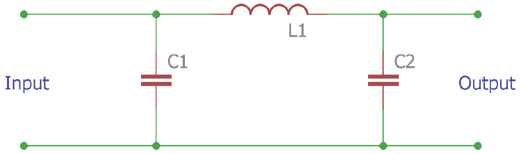
As seen in the above image, it consists of two capacitors which are connected to ground with an in-between series inductor. As this is a low pass filter, it produces high impedance at high frequency and low impedance at low frequency. Thus, it is commonly used in a transmission line to block unwanted high frequencies.
The construction and the component values of the Pi filter calculation can be derived from the below equation to design a Pi Filter for your application.
Cut off frequency(fc) = 1/ᴫ(LC)1/2
Value of the Capacitance is (C) = 1/Z0ᴫfc
Value of the inductance (L1) = Z0/ᴫfc
Where, the Z0 is the impedance characteristic in ohms and fc is the cut off frequency.
Pi Filter as a High Pass Filter
Same as the low pass filter, pi filters can also be configured as a high pass filter. In such a case, the filter blocks the low frequency and allows the high frequency to pass. It is also made using two types of passive components, two inductors, and one capacitor.
In low pass configuration the filter is designed as two capacitors are in parallel with an inductor in between, but in high pass configuration, the position and the quantity of the passive components get exactly the opposite. Instead of a single inductor, here two separate inductors are used with a single capacitor.
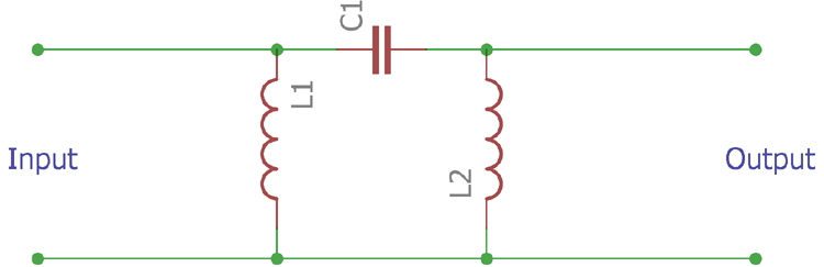
The above Pi Filter circuit image is showing the filter in high pass configuration, and not to mention the construction is also looking like a symbol Pi. The construction and the component values of the Pi filter can be derived from the below equation –
Cut off frequency (fc) = 1/4ᴫ(LC)1/2
Value of the capacitance is (C) = 1/4Z0ᴫfc
Value of the impedance (L1) = Z0/4ᴫfc
Where, the Z0 is the impedance characteristic in ohms and fc is the cut off frequency.
Advantages of the Pi Filter
High output voltage
The output voltage across the pi filter is quite high making it suitable for the most power related application where high voltage DC filters are required.
Low ripple factor
Configured as a low pass filter In DC filtration purposes, Pi filter is an efficient filter, to filter out unwanted AC ripple coming from a bridge rectifier. The capacitor provides low impedance in AC but a high resistance in DC due to the effect of capacitance and reactance. Due to this low impedance across AC, the first capacitor of the Pi filter bypasses the AC ripple coming from the bridge rectifier. The bypassed AC ripple goes into the inductor. The inductor resists the changes of current flow and blocks the AC ripple which his further filtered by the second capacitor. These multiple stages of filtering help to produce a very low ripple smooth DC output across the Pi filter.
Easy to design in RF applications
In a controlled RF environment, where higher frequency transmission is required, for example in the GHz band, High-Frequency Pi filters are easy and flexible to make in the PCB using just PCB traces. High-frequency Pi filters also provide surge immunities more than the silicon-based filters. For instance, a silicon chip has a limit of voltage withstand capacity, whereas pi filters made using the passive components have much more immunity in terms of surges and harsh industrial environments.
Disadvantages of the Pi Filter
Higher Wattage Inductor Values
Other than the RF design, High current draw through a Pi filter is not advisable since the current has to flow through the Inductor. If this load current is relatively high, then the wattage of the Inductor also increases making it bulky and expensive. Also, the high current through the inductor increases the power dissipation across the inductor resulting in poor efficiency.
High-value Input Capacitor
Another major problem of the Pi filter is the large input capacitance value. Pi filters require high capacitance across the input which became a challenge in space-constrained applications. Also, high-value capacitors increase the cost of the design.
Bad Voltage Regulation
Pi filters are not suitable where load currents are not stable and constantly changing. Pi filters provide bad voltage regulation when load current drifts a lot. In such an application the filters with an L section are recommended.
Application of Pi Filters
Power Converters
As already discussed, Pi filters are an excellent DC filter to suppress the AC ripples. Due to this behavior, Pi filters are extensively used in Power Electronic designs like AC-DC converter, Frequency converter, etc. However, in Power Electronics Pi Filters are used as Low Pass Filter and we already designed a Pi Filter Power supply Circuit, for our 12V 1A SMPS Design as shown below.
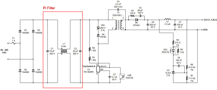
Generally, Pi filters are directly connected with the bridge rectifier and the output of the Pi filters is referred to as the High Voltage DC. The output DC High Voltage is used for the Power supply driver circuitry for further operation.
This construction, from Bridge rectifier diode to the driver has a different operation with the working of Pi-Filter. First, this Pi filter provides smooth DC for the ripple-free operation of the overall driver circuit resulting in a low output ripple from the final output of the power supply, and the other one is for isolating main lines from the high switching frequency across the driver circuit.
A properly constructed line filter can provide Common-mode filtration (A filter that rejects noise signal as if an independent single conductor) and differential mode filtration (differentiating two switching frequency noise, especially high-frequency noise that can be added into the mains line) in a Power supply where Pi filter is an important component. A pi filter is also referred to as a Power Line filter if used in Power Electronics Application.
RF Application
In the RF application, Pi filters are used in different operations and different configurations. For example, in RF applications, matching impedance is a huge factor and Pi filters are used to match impedance across the RF Antennas and before RF amplifiers. However, in maximum cases where very high frequency, such as in the GHz band is used, Pi filters are used in the signal transmission line and designed using only PCB traces.
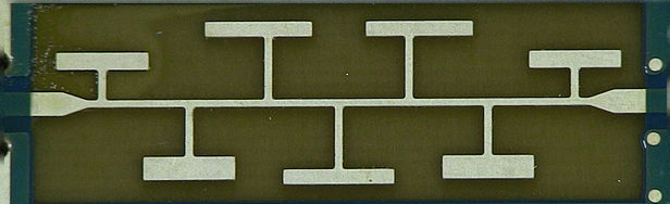
The above image is showing PCB trace-based filters where the trace creates inductance and capacitance in very high-frequency applications. Other than the transmission line, Pi filters are also used in RF communication devices, where modulation and demodulation take place. Pi filters are designed for a targeted frequency to demodulate the signal after receiving in the receiver side. High pass Pi filters are also used to bypass targeted high frequency into the amplification or transmission stages.
Pi-Filter Design Tips
To design a proper Pi filter it is required to compensate proper PCB design tactics for trouble-free operation, these tips are listed below.
In Power Electronics
- Thick traces are required in the Pi filter layout.
- Isolating the Pi filter from the power supply unit is essential.
- The distance between the input capacitor, inductor, and the output capacitor is needed to be closed.
- The Ground plane of the output capacitor is needed to be directly connected to the driver circuit via a proper ground plane.
- If the design consists of noisy lines (Such as high voltage sense line for the driver) that is need to be connected across High voltage DC, it is required to connect the trace before the final output capacitor of the Pi filters. This improves noise immunity and unwanted noise injection across the driver circuitry.
In RF Circuit
- The component selection is a major criterion for the RF application. The tolerance of the components plays a major role.
- A small increase in the PCB trace could induce inductance in the circuit. Proper care should be taken for inductor selection by considering PCB trace inductance. The design should be made using proper tactics to reduce stray inductance.
- Stray capacitance is needed to be minimized.
- Closed placement is required.
- Coaxial cable is suitable for the input and output in the RF application.

Hi team,
Your web content is great. It is very much helpful for learners. While going through your site, I noticed that the "Passive High Pass Filter" and "Passive Low Pass Filter" link is swapped. While clicking the Low pass link it's going High pass page.