

Previously we described about Passive High Pass Filter and Active Low Pass Filter, now it is time for Active High pass filter. Let’s explore what is an Active High Pass Filter.
What is it, Circuit, formulas, curve?
Same as like passive low pass filter, passive high pass filter works with passive components, Resistor and Capacitor. We learned in the previous tutorial about passive high pass filter that its work without any outer interruption or active response.
If we add an Amplifier across passive high pass filter, we can easily create Active high pass filter. Changing the amplifier configuration we can also form different types of high pass filter, inverted or non-inverted or unity gain active high pass filter.
For the sake of simplicity, time effectiveness and also the growing technologies in op-amp design, generally an op-amp is used for Active Filter design.
In passive high pass filter, the frequency response is infinite. But in the practical scenario it highly depends on components and other factors, here in the case of active high pass filter, the op-amp bandwidth is the main limitation of active high pass filter. That means the maximum frequency will pass depending on the gain of the amplifier and the open-loop characteristic of the op-amp.
Let’s explore few common op-amps open-loop Dc voltage gain.
| Op-amp | Bandwidth(dB) | Maximum Frequency |
| LM258 | 100 | 1MHz |
| uA741 | 100 | 1MHz |
| RC4558D | 35 | 3MHz |
| TL082 | 110 | 3MHz |
| LM324N | 100 | 1MHz |
This is a small list about generic op-amp and there voltage gain. Also, the voltage gain is largely dependable on the frequency of the signal and the input voltage of the op-amp and how much gain is applied in that op-amp.
Let’s Explore further and understand what is special about it:-
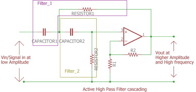
Here is the Simple High Pass Filter Design:-
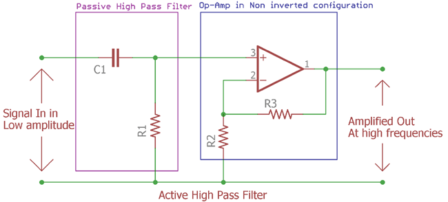
This is the image of Active High pass filter. Here the violate line shows us the traditional passive High pass RC filter we seen in previous tutorial.
Cut off Frequency and Voltage gain:
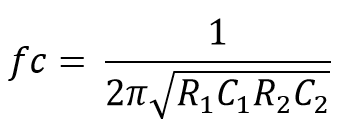
The Cut off frequency formula is same as used in passive High pass filter.
fc = 1 / 2πRC
As described in previous tutorial fc is the cut-off frequency and the R is Resistor value and the C is Capacitor value.
The two resistor connected in the positive node of the op-amp are feedback resistors. When these resistors are connected in positive node of the op-amp it is called non-inverting configuration. These resistors are responsible for the amplification or the gain.
We can also easily calculate the gain of the amplifier using the following equations where we can choose the equivalent resistor value according to gain or it can be vice-versa:-
Amplifier Gain (DC amplitude)(Af) = (1 + R3/R2)
Frequency Response Curve:
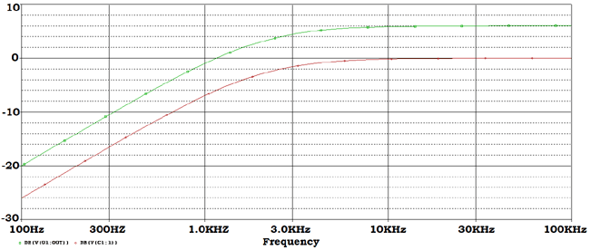
Let’s see what will be the output of the Active High pass filter or the Bode plot/Frequency response curve:-
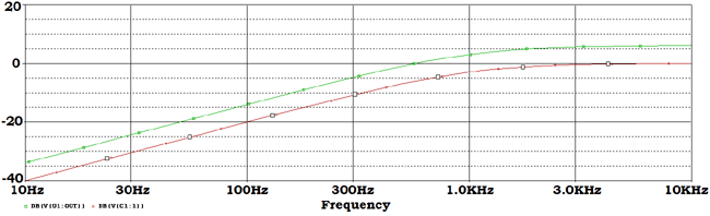
This is the gain curve of the op-amp and the filter connected across the amplifier.
This green curve shows the amplified output of the signal and the red one shows the without amplified output across passive high pass filter.
If we see the curve more accurately then we will find the below points inside this bode plot:-
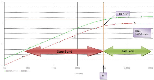
The red curve increase at 20dB / decade and in the cutoff region the magnitude is -3dB which is 45 degree phase margin.
As discussed before that the maximum frequency response of an op-amp is highly connected with it’s gain or bandwidth (as called open-loop gain Av).
In the list provided before we have seen typical common op-amp like uA741, LM324N have 100dB maximum open loop gain which will reduce at a roll-off rate of -20dB per Decade if the input frequency increase. The maximum input frequency supported by LM324N, uA741 is 1 Mhz, which is unity gain bandwidth or frequency. At this frequency the respective op-amp will produce 0dB gain or unity gain decreasing 20dB/decade.
So it is not infinite, after 1 MHz the gain will decrease at the rate of -20dB/decade. The Bandwidth of the active high pass filter is highly dependent on bandwidth of the op-amp.
We can calculate the magnitude gain by converting the op-amp Voltage gain.
The calculation is as follows:-
dB = 20log(Af) Af = Vin / Vout
This Af can be the Dc gain we described before by calculating the resistor value or dividing the Vout with Vin.
We can also obtain the voltage gain from the frequency applied to the filter (f) and the cut-off frequency (fc). Deriving the voltage gain from this two is very simple using this formula =
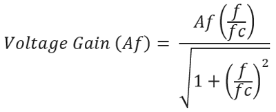
If we put the value of f and fc we will get the desired voltage gain across the filter.
Inverting Amplifier Filter Circuit:
We can also construct the filter in inverted formation.
The Phase margin can be obtained by the following equation.
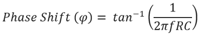
The Phase shift is same as seen in Passive high pass filter. It is +45 degree at the cutoff frequency of fc.
Here is the circuitry implementation of inverted active High pass filter:-
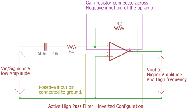
It is an active High pass filter in inverted configuration. The op-amp is connected inversely. In the previous section the input was connected across op-amp’s positive input pin and the op-amp negative pin is used to make the feedback circuitry. Here the circuitry inverted. Positive input connected with ground reference and the capacitor and feedback resistor connected across op-amp negative input pin. This is called inverted op-amp configuration and the output signal will be inverted than the input signal.
The resistor R1 is acting as a role of passive filter and also as a gain resistor both at once.
Unity Gain or Voltage Follower Active High Pass Filter:
Till now the circuitry described here is used for voltage gain and post amplification purpose.
We can make it using a unity gain amplifier, that means the output amplitude or gain will be 1x. Vin = Vout.
Not to mention, it is also an op-amp configuration which often described as voltage follower configuration where the op-amp create exact replica of the input signal.
Let’s see the circuit design and how to configure the op-amp as voltage follower and make the unity gain active High pass filter:-
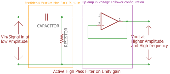
In this image everything is identical as gain amplifier used in first figure. the feedback resistors of the op-amp are removed. Instead of the resistor the negative input pin of the op-amp connected directly with the output op-amp. This op-amp configuration is called as Voltage follower configuration. The gain is 1x. It is a unity gain active High pass filter. It will produce exact replica of the input signal.
Practical example with Calculation
We will design a circuitry of active High pass filter in non-inverting op-amp configuration.
Specifications:-
- Gain will be 2x
- Cutoff freq will be 2KHz
Let’s calculate the value first before making the circuitry:-
Amplifier Gain (DC amplitude)(Af) = (1 + R3/R2)
(Af) = (1 + R3/R2)
Af = 2
R2= 1k (We need to select one value; we selected 1k for reducing the complexity of the calculation).
By putting the value together we get
(2) = (1 + R3/1)
We calculated the value of third resistor (R3) is 1k.
Now we need to calculate the value of the resistor according to the cut-off frequency. As active High pass filter and the passive High pass filter works on the same way the frequency cut-off formula is same as before.
Let’s check the value of the capacitor if the cut-off frequency is 2KHz, we selected the value of the capacitor is 0.01uF or 10nF.
fc = 1/2πRC
By putting all value together we get:-
2000 = 1 / 2π*10*10-9
By solving this equitation we get the value of the resistor is 7.96 approximately.
The nearest value is selected of this resistor 8k Ohms.
Next step is to calculate gain. The formula of the gain is same as passive High pass filter. The formula of gain or magnitude in dB is as follows:-
As the gain of the op-amp is 2x. So the Af is 2.
fc is cut off frequency so the value of fc is 2Khz or 2000Hz.
Now changing the frequency (f) we get the gain.
|
Frequency(f) |
Voltage Gain (Af) (Vout/Vin) |
Gain(dB) |
|
100 |
.10 |
-20.01 |
|
250 |
.25 |
-12.11 |
|
500 |
.49 |
-6.28 |
|
750 |
.70 |
-3.07 |
|
1,000 |
.89 |
-0.97 |
|
2,000 |
1.41 |
3.01 |
|
5,000 |
1.86 |
5.38 |
|
10,000 |
1.96 |
5.85 |
|
50,000 |
2 |
6.01 |
|
100,000 |
2 |
6.02 |
In this table from the 100 Hz the gain is sequentially increased in a pace of 20dB/decade but after the cutoff frequency is reached the gain is slowly increased to 6.02dB and remains constant.
One thing to remind that the Gain of the op-amp is 2x. For that reason the cut off frequency is: -3dB to 0dB (1x gain) to +3dB (2x gain)
Now as we already calculated the values now it is the time to construct the circuit. Let’s add all together and build the circuit:-
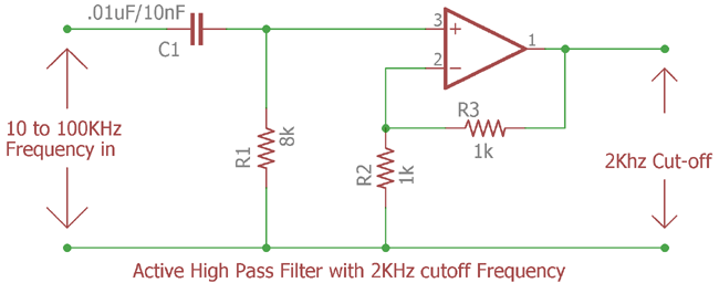
We constructed the circuit based on the values calculated before. We will provide 10Hz to 100KHz frequency and 10 points per decade at the input of the active High pass filter and will investigate further to see whether the cutoff frequency is 2000Hz or not at the output of the amplifier
This is the frequency response curve. The green line is representing Amplified output of the filter which is 2 x gains. And the red line representing the filter response across input of the amplifier.

We set the cursor at the 3dB the corner frequency and get 2.0106 KHz or 2 KHz.
As described before the passive filter gain -3dB but as 2x gain of op-amp circuitry added across filtered output, the cutoff point is now 3dB as 3dB added two times.
Cascading and adding More Filters to One Op-Amp
It’s possible to add more filters across one op-amp like second order active High pass filter. In such case just like the passive filter, extra RC filter is added.
Let’s see how the Second Order Active High Pass Filter Circuit is constructed.
This is the Second order filter. In the figure we can clearly see the two filters added together. This is the second order high pass filter.
As you can see there is one op-amp. The voltage gain is same as previously stated using two resistors. As the gain formula is same the Voltage gain is
Af = (1 + R2/R1)
The cut-off frequency is:-
We can add higher order high pass active filter. But there is one rule.
If we want to make a third order filter we can cascade first and second order filter.
Same as like two Second –order filter create fourth order filter and this sums is added up each time.
Cascading Active High Pass Filter can be done by as follows:-
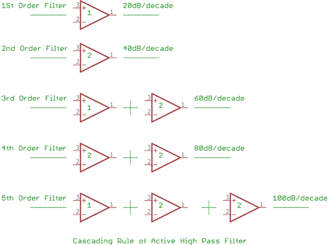
The more the op-amp added the more gain is added. See the above figure. The numbers written on the op-amp are representing the order stage. Like 1 = 1st order stage, 2= 2nd order stage. Each time the stage is added the gain magnitude also added by 20dB/decade for each stage is added. Like for the first stage it is 20dB/decade, 2nd Stage it is 20dB + 20dB = 40dB per decade etc. Every even number filter consists second order filters, every odd number consists first order and second order filter, first order filter on the first position. There are no limitations to how many filters can be added, but it is the accuracy of the filter which decreases when extra filters are added subsequently. If the RC filter value i.e. Resistor and capacitors are same for each filter, then the cut-off frequency will be same also, the overall gain is remain equal as the frequency components used are same.
Applications
Active High pass filter can be used at multiple places where passive High pass filter cannot be used due to the limitation about gain or amplification procedure. Apart from that the active High pass filter can be used in following places:-
High pass filter is widely used circuit in electronics.
Here are few applications:-
- Treble equalization before Power amplification
- High frequency Video related filters.
- Oscilloscope and Function generator.
- Before Loud speaker for removing or reducing the Low frequency noise.
- Changing the frequency shape at different wave from.
- Treble boost filters.
