

Previously, we discussed the Passive Low Pass Filter; now it is time to look into the passive high pass filter. A passive high pass filter is an electronic circuit that allows high-frequency signals to pass while blocking low frequencies below a predetermined cutoff point.
Same as before, if you look into the name, it shows “Passive”, “High”, “Pass” and “Filter”. So, as the name suggests, it is a filter that will block Low frequencies, but pass the high frequencies above the predetermined value, which will be calculated by the formula.
Table of Contents
What is a Passive High Pass Filter?
It is “passive”, which means no external power, no amplification of the input signal; we will make the circuit using “passive” components, which do not require any external power source. The passive components are the same as Low pass filter, but the connection order will be exactly reversed. The passive components are the Resistor (R) and the Capacitor (C). Again, it is an RC filter configuration. A passive high pass filter is a frequency-selective circuit that permits signals above a specific frequency (cutoff frequency) to pass through while attenuating lower frequencies
Key Characteristics of a High Pass Passive Filter
| Parameter | Description | Value/Range |
| Components Required | Resistor (R) and Capacitor (C) | Non-polarized components |
| Power Requirement | No external power needed | Passive operation |
| Frequency Response | Blocks low frequencies, passes high frequencies | Above cutoff frequency (fc) |
| Phase Shift | Positive phase shift | +45° at cutoff frequency |
| Roll-off Rate | First order: +20dB/decade | Second order: +40dB/decade |
Passive High Pass Filter Circuit Diagram
The passive high pass filter circuit diagram shows a simple RC configuration. Let’s see what happens if we construct the circuit and check the response or “Bode Plot”…Here is the circuit in this image:
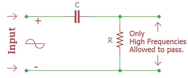
This is an RC filter. Generally, an input signal is applied to this series combination of a non-polarised capacitor and a resistor. It is a first-order filter as there is only one reactive component in the circuitry, that is, a capacitor. The filtered output will be available across the resistor. The combination of these two is exactly the opposite of low pass filter. If we compare the circuit with the low pass filter we will see that the position of the resistor and the capacitor is interchanged.
Passive High Pass Filter Working Principle
At low frequencies, the reactance of the capacitor will be so large that it will act like an open circuit and block the input signal below the cut-off frequency point (fc). But when the cut-off frequency point is reached, the reactance of the capacitor will start to reduce and allow the signal to pass directly. We will see this in detail in the frequency response curve.
The passive high pass filter working principle is based on the frequency-dependent behaviour of capacitive reactance:-
First Order Passive High Pass Filter
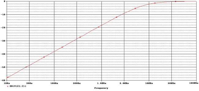
A first order passive high pass filter contains only one reactive component (a capacitor) in the circuit. This is the frequency response curve of that first order high pass filter circuit.
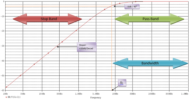
fc Is the cutoff frequency of the filter. At the -3 dB point, the signal is allowed to pass. This -3 dB also denotes the cutoff frequency. From 10Hz to the cut-off frequency, the signal is not allowed to pass as the frequency is too low. At this point, it is the stop band portion where the signal is not allowed to pass through the filter, but above the cut-off frequency, after -3 dB, the portion is called the pass band portion where the signal is allowed to pass. The slope of the curve is +20dB per decade. Exactly opposite of Low low pass filter.
First Order Filter Characteristics
| Parameter | First Order High Pass Filter |
| Components | 1 Resistor + 1 Capacitor |
| Roll-off Rate | +20dB/decade (+6dB/octave) |
| Phase Shift at fc | +45° |
| Maximum Phase Shift | +90° |
| Order | n = 1 |
The formula for calculating gain is the same as we used in our previous tutorial on a passive Low pass filter.
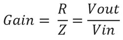
Gain(dB) = 20 log (Vout / Vin)
After the cut-off signal, the responses of the circuit gradually increase to Vin from 0, and this increment happens at a rate of +20dB/Decade. If we calculate the increase per octave, it will be 6dB.
This Frequency Response Curve is the Bode Plot of a high pass filter. By selecting a proper capacitor and a proper resistor, we could stop Low frequencies, limit signal passing through the filter circuitry without affecting the signal, as there is no active response.
In the above image, there is a word Bandwidth. It signifies the frequency that the signal will allow to pass. So, if it is a 600 kHz high pass filter, then the bandwidth will be from 600Khz to Infinity. As it will allow all signals above the cut-off frequency.
At the cut-off frequency, we will get -3 dB gain. At that point, if we compare the output signal amplitude with the input signal, then we will see that the output signal amplitude would be 70.7% of the input signal. Also, in -3 dB gain, the capacitive reactance and resistance would be equal. R= Xc.
Passive High Pass Filter Cutoff Frequency Formula
The passive high pass filter cutoff frequency determines the boundary between the stop band and the pass band regions. The formula of the Cut-off frequency is the same as that of a low pass filter.
fc = 1 / 2πRC
So, R is resistance and C is capacitance. If we put the value, we will know the cutoff frequency.
Output Voltage Calculation
Let’s see the first image, the circuitry where 1 resistor and one capacitor are used to form a high pass filter or RC circuit.
When a DC signal is applied across the circuit it’s resistance of the circuit creates a drop when current is flowing. But in the case of an AC signal, it’s not resistance but impedance that is responsible for voltage drop, which is measured in Ohms, too.
In the RC circuit, there are two resistive things. One is resistance, and the other is the capacitive reactance of the capacitor. So, we need to measure the capacitive reactance of the capacitor first, as it will be needed to calculate the impedance of the circuitry.
Capacitive Reactance Formula
First resistive opposition is capacitive reactance, the formula is:-
Xc = 1 / 2πfC
The output of the formula will be in Ohms, as Ohms is the unit of capacitive reactance because it is an opposition, meaning Resistance.
The Second opposition is the resistor itself. The value of a resistor is also a resistance.
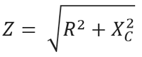
So, combining these two oppositions, we will get the total resistance, which is impedance in the RC (AC signal input) circuit.
Impedance is denoted as Z
Gain Formula
The Formula is:-
As discussed before, at low frequency the reactance of the capacitor is too high that it is act as an open circuit, the reactance of the capacitor is so high that it acts as an open circuit; the reactance of the capacitor is Infinity at low frequency, so it blocks the signal. Output gain is 0 at that time, and due to the block, the output voltage remains 0 until the cut-off frequency is reached.
But in High frequency, the opposite will happen. The reactance of the capacitor is so low that it acts as a short circuit; the reactance of the capacitor is 0 at high frequency, so it passes the signal. Output gain is 1 at that time, that is a unity gain situation, and due to unity gain, the output voltage is the same as the input voltage after the cut-off frequency is reached.
Example with Calculation
As we already know what is actually happening inside the circuit and how to find out the value. Let’s choose practical values.
Let’s pick up the most common value in the resistor and the capacitor, 330k and 100pF. We selected the value as it is widely available and it is easier to calculate.
Let’s see what the cut-off frequency is and what the output voltage will be.
Cut off Frequency will be:-
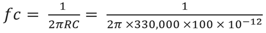
By solving this equation, the cut-off frequency is 4825Hz or 4.825KHz.
Let’s see whether it is true or not…
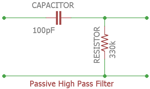
This is the circuit of the example.
As the frequency response described before, at the cut-off frequency, the dB will be -3 dB, Irrespective of the frequencies. We will search for -3 dB at the output signal and see whether it is 4825Hz (4.825Khz) or not.
Here is the frequency response:-
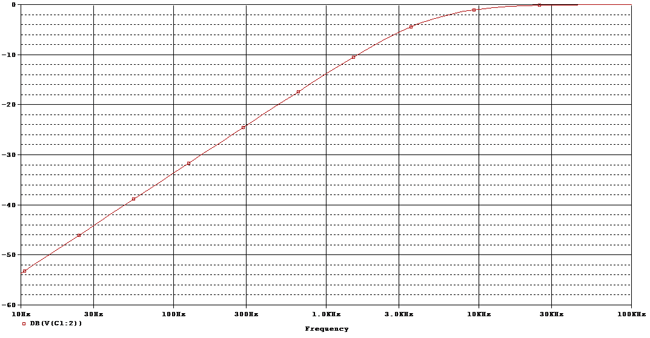
Let’s set the cursor at -3 dB and see the result.

As we can see, the Frequency response (Also called the Bode Plot), we set the cursor at -3.03 dB and get 4.814KHz Bandwidth Frequency.
Phase Shift Formula
Phase Angle, denoted as φ (Phi), will be at the output, +45° from the input signal, at -3 dB or Cut-Off frequency.
The frequency response of the filter shows us that it could pass all signals above the cut-off frequency to infinity. It is just theoretical practice. In the practical and real world, the passband is limited by the limitations of practical components.
The formula of Phase shift is not the same as Low Pass filter, as in a low pass filter, the phase becomes negative, but in high pass filter, it is a positive phase shift, so the formula implies:-
Phase shift φ = arctan (1 / 2πfRC)
Let’s see the phase shift curve of the circuit:-

This is the Phase shift of the circuit, used as a practical example.
Let’s find out the phase shift value at the cut-off frequency:-

We set the cursor at +45° and get the result of the cut-off frequency 4.82KHz.
Time constant
As we already learn before about phase shift and frequency response, the capacitor gets a charging and discharging effect from the input signal frequencies. This charging and discharging effect is the Time Constant, denoted as τ (Tau). It is also related to the cut-off frequency.
How?
τ = RC = 1 / 2πfcSometimes we need to know the cut-off frequency when we have the time constant value. In such a case, by altering the formula, we can easily get that:-
fc = 1 / 2πRC
Where RC = τ
fc = 1 / 2πτ
Effect of Time Constant in High Pass Filter:
The High Pass filter is a Differentiator. If we feed a Square Wave and provide it in a perfect time domain, the output waveform of the filter produces spikes or a short-duration pulse. If the time constant is short, the filter will produce a differentiated square wave. We can differentiate a signal using this property of High Pass Filter.
Second Order Passive High Pass Filter: Formulas, Calculations and Frequency Curves
A second order passive high pass filter is created by cascading two first-order RC stages, providing steeper roll-off characteristics. When a two first order low pass RC stage circuit is cascaded together, it is called a second order filter as there are two RC stage networks.
Here is the circuit:-
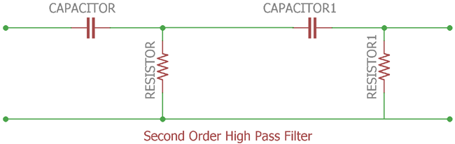
This is a second order High Pass Filter. CAPACITOR and RESISTOR are the first order, and CAPACITOR1 and RESISTOR1 are the second order. Cascading together, they form a second order High pass filter.
Second order filter has a slope of 2 x +20dB/decade or +40dB (12dB/octave).
Here is the response curve:-
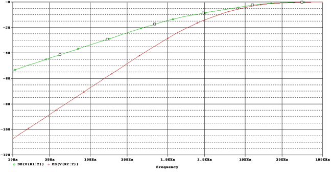
The slope is +20dB/ Decade, and the red one at the final output has a slope of +40dB/Decade.
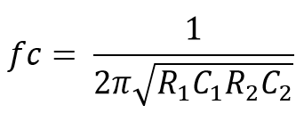
This will calculate the cut-off frequency of the second-order High pass circuit.
Just like Low Pass filter, it’s not so good to cascade two passive High Pass filters, as the dynamic impedance of each filter order affects the other network in the same circuitry.
Passive High Pass Filter Applications
A high pass passive filter is a widely used circuit in electronics.
Here are a few applications:-
- Audio receiver and Equaliser
- Music control system and Treble frequency modulation.
- Function Generator
- Cathode Ray Television and Oscilloscope.
- Square Wave Generator from a Triangular wave.
- Pulse Generators.
- Ramp to Step Generators.
Frequently Asked Questions: High Pass Passive Filter
⇥ What is the difference between passive and active high pass filters?
Passive high pass filters employ just resistors and capacitors without a power supply, whereas active filters have operational amplifiers, which need a power supply. Active filters offer amplification of gain and improved performance.
⇥ Why is the phase shift positive in high pass filters?
High pass filters cause a positive phase shift since the capacitor precedes the resistor in phase. Phase shift is +45° at the cutoff frequency, rising to the maximum +90° at very low frequencies.
⇥ How do you improve selectivity of passive high pass filters?
To improve filter selectivity, increase filter order by cascading filter stages and/or use higher-order filter topologies. Each additional order will provide a 20dB/decade steeper roll off, increasing frequency selectivity and stop band attenuation.
⇥ Are you able to cascade several passive high pass filter stages?
Yes, but each stage loads the previous one and degrades overall performance. Second-order filters give +40dB/decade roll-off but might need buffer amplifiers for best operation.
⇥ What is the bandwidth of high pass filter?
In theory, bandwidth extends from the cutoff frequency to infinity. In practice, bandwidth is constrained by component parasitics and circuit limitations at very high frequencies.
⇥ In what way does temperature change the performance of passive high pass filters?
With temperature changes, component values - especially capacitance values - will change accordingly as well. Temperatures are not as stable as ceramic or film capacitors, so the cutoff frequency remains stable across temperature ranges.
⇥ What happens to gain above the cutoff frequency in passive high pass filters?
Gain approaches 1 (0dB) at or above the cutoff frequency because at these frequencies, capacitive reactance is nearly zero. A high pass filter allows high frequencies to pass unhindered and without phase distortion.
The Conclusion
Passive high pass filter offers a great, cost-effective implementation for any high-frequency signal processing application. Understanding the passive high pass filter formula, circuit layout, and operation allows you to adequately engineer a design that meets your frequency requirements, whether it be first order passive high pass filter or second order passive high pass filter, and the application specifications with which it is combined.
The passive high pass filter calculator method shown above, along with real circuit experiences, can set you on the right path to bring about success in implementing filter designs in your electronics applications.
Interesting Projects Built with Filter
Our past projects showcase practical uses of filters, check out the links below for details.

Butterworth Filter: First Order and Second Order Low Pass Butterworth Filter
Electric filters have many applications and are extensively used in many signal processing circuits. It is used for choosing or eliminating signals of selected frequency in a complete spectrum of a given input. So the filter is used for allowing signals of chosen frequency to pass through it or eliminating signals of chosen frequency from passing through it.

So in this tutorial, we will learn about this Band Pass filter, the theory behind it and how it can be used in practical circuits.

Pi Filter - Overview, Working, Construction, Application and Design Tips
In this tutorial, we learn another new type of filter called the Pi Filter, which is very commonly used in power supply circuit designs. We have already used Pi-Filter in a few of our previous Power supply designs, like this 5V 2A SMPS circuit and 12V 1A SMPS Circuit.
