The History of Arduino Part 2: Revolutionizing Embedded Electronics
Shields Up! New Boards Incoming!
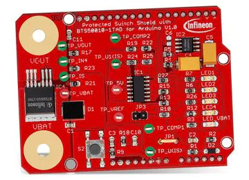
It is arguable that a significant contributing factor to the success of Arduino, especially in its earliest days, was the cottage industry of complementary boards created and sold by third parties. These boards, known as shields, could be inserted into the unique headers of the Arduino form factor found onboard the Diecimila, Duemilanove, and current generation Uno boards. They helped to expand the functionality of the underlying Arduino board by allowing designers to quickly integrate a variety of sensors and actuators into their Arduino-based projects. The interoperability and the ability to nest multiple shields proved a decisive victory for Arduino. Indeed, today many other embedded system manufacturers offer development boards that feature compatibility with Arduino shields (Figure 1).
The popularity of the original Arduino form factor did not prevent the company from introducing a variety of additional form factors that retained the ease of tinkering and programming. The electronics at the heart of the Arduino board have evolved over the years. Newer microcontrollers have been incorporated to provide more processing horsepower. Over the years, hardware has been added to provide increased functionality, such as Wi-Fi® and BLUETOOTH® wireless communications. Arduino has even released technology and curriculum bundles aimed at teaching science and robotics courses. Some of the highlights from the years of hardware evolution are:
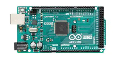
Mega: Physically a much larger board than the Uno that exposed significantly more I/O pins (the current revision has 54 digital I/O pins, 16 analog inputs, and 4 UARTs) to give the designer more flexibility and to create more complex systems (Figure 2).
Micro and Nano: As their names imply, Micro and Nano form factors are much smaller than the Uno form factor. The smaller form factor made them preferable for final designs or applications with significant size restraints.
Lilypad: Explicitly created for those with an interest in wearable electronics. Conductive thread replaces traditional wire as the means of connecting components.
MKR: The MKR line of boards is arguably the first attempt of Arduino to bridge the maker and professional markets. While the MKR family shares a compact common form factor, it offers a wide variety of architectures, communications protocols, shield-based sensors, actuators, and system interfaces. For example, there are MKR boards with Wi-Fi, LoRa, and GSM wireless protocols. In addition, there are shields for interacting with DC motors, CANbus, and RS–485 industrial protocols.
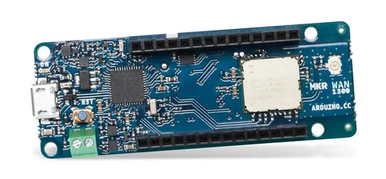
VIDOR 4000: The VIDOR was Arduino’s first attempt at Field Programmable Gate Array (FPGA) hardware versus microcontrollers. While the VIDOR shared the same Cortex-M0 32-bit SAMD21 as other MKR boards and was thus programmable via the Arduino IDE, the FPGA-side of the board never really fulfilled the promise of bringing hardware description languages (HDL) such as Verilog and VHDL to the masses. Though using industrial-strength tools, it is possible to program the VIDOR with HDL; it has never proven to be something that most makers (or even professionals) have really tried to attempt.
Portenta: The Portena line of embedded system products marked Arduino’s expansion into hardware for dedicated professional development. Portenta brings numerous hardware improvements that make it preferable for industrial applications such as factories and automobiles. In addition, built-in support for wireless protocols such as Wi-Fi, BLE, LoRa, LTE Cat-M, and NB-IoT and legacy wired protocols such as RS-485 means Arduino can help bridge the gap between the old and the new, ensuring reliability while also adding new functionality such as machine learning and digital twins. Furthermore, the seeds of Arduino’s investment in the education market will sow countless rewards as young people who learned about electronics using an Arduino Uno will have less of a learning curve with the newer professional-grade Arduino products.
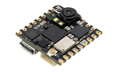
Nicla: The Nicla also falls under the professional umbrella, with the Nicla Vision focusing on AI-based computer vision applications (Figure 4). The almost stamp-sized form factor with the built-in camera means the Nicla Vision can be easily integrated into existing machinery with minimum fuss. The Nicla Sense ME has the same form factor while providing professional-grade motion and environmental sensing capability.
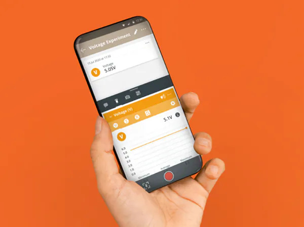
In the late 2010s, Arduino made moves to expand from just a hardware manufacturer to a full-fledged embedded systems ecosystem. 2019 saw the release of an online test-based certification program that allowed individuals to prove their knowledge of basic electronics, software development, and certain aspects of the Arduino ecosystem. Then in September 2020, Arduino took ownership of Google’s Science Journal smartphone application used in many science curricula (Figure 5). They even expanded the app's capability to use not just the onboard smartphone sensors but also sensors found aboard the Arduino Nano 33 BLE Sense development board.
Arduino Today, Arduino Tomorrow
As we find ourselves rapidly approaching the beginning of Arduinos third decade, it is pretty remarkable to look back at the growth of an ecosystem that has already revolutionized electronics education and is well-positioned to do much more in the future. Today Arduino is much more than an artist-designed 8-bit microcontroller-based circuit board and barebones software development environment. Indeed, they are keeping pace, if not leading the charge, in moving embedded systems technology into the future.
There are two major trends that embedded systems developers must continue to appreciate and invest in if they wish to remain competitive. The first is the push of AI technology (such as machine learning) to the “edge,” meaning embedded electronics right at the point of action, far removed from relying on high-end servers to do all the computationally intensive processing. The Portenta and Nicla products mentioned earlier, along with partnerships with companies such as Edge Impulse, show that Arduino has no intention of resting on its laurels and is embracing AI technology.
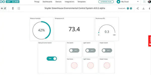
The second trend is the continuing incremental rollout of the Internet of Things and the recent emergence of technologies explicitly built for IoT, such as Thread. In recent years, Arduino embraced the cloud and IoT (Figure 6). Starting as Arudino Create before being rebranded as Arduino Cloud in 2021, the hosted service gives developers a convenient cloud-based platform to remotely monitor and control Arduino-based solutions. Arduino made this even more convenient with the release of their IoT Remote smartphone applications available for both iOS and Android.
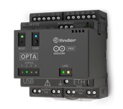
The future is looking bright for Arduino. In the course of researching and writing this article, additional significant announcements were made regarding future Arduino hardware and services. First, the company just announced Opta, their first-ever Programmable Logic Controller (PLC) for industrial applications (Figure 7). The Opta will be programmable using industry-standard ladder logic diagrams and function block diagrams. Additionally, the company announced Arduino Cloud for Business. In a way that mirrors how the Pro line of products moved Arduino into industrial-grade hardware, Arduino Cloud for Business will transform Arduino Cloud in a similar manner. In addition, the business offering will include features that will make Arduino-based edge devices easier to securely provision, monitor, and update at scale.
Happy 20th Birthday, Arduino!
2023 marks Arduino’s 20th year of existence. So much has changed in our world in the intervening years. Then, there were no iPhones or Android devices, Netflix was a company that sent you DVDs via snail mail, and embedded systems were the purview of large corporations and the most tenacious hobbyists. Today we live in a world where almost anyone interested in electronics can get involved in a very hands-on way. And while Arduino is not the only company to help create this modern world, it certainly casts a big shadow for a small company started by five people at a small academic institution in Ivrea, Italy. So here is to the next twenty years, Arduino.
Oroginal Source: Mouser
About the Author
 Michael Parks, P.E. is the co-founder of Green Shoe Garage, a custom electronics design studio and embedded security research firm located in Western Maryland. He produces the Gears of Resistance Podcast to help raise public awareness of technical and scientific matters. Michael is also a licensed Professional Engineer in the state of Maryland and holds a Master’s degree in systems engineering from Johns Hopkins University.




 After completing his studies in electrical engineering, Jon Gabay has worked with defense, commercial, industrial, consumer, energy, and medical companies as a design engineer, firmware coder, system designer, research scientist, and product developer. As an alternative energy researcher and inventor, he has been involved with automation technology since he founded and ran Dedicated Devices Corp. up until 2004. Since then, he has been doing research and development, writing articles, and developing technologies for next-generation engineers and students.