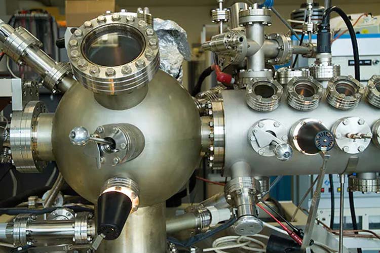
For engineers who spend their design time in the single-digit, low-voltage world, the phrase "high voltage" may conjure up voltages in the double digits, perhaps as high as 24V or 48V DC, or even the triple-digit domain of line voltages of 120/240 VAC. Yet there's a huge and essential world of engineering design that must be done at 1000V, 1500V, and higher voltages.
Designing products for this region calls for very different thinking, component selection, and interconnection, often in areas designers of low-voltage products do not have to even consider. These concerns apply to passive components, connectors, wiring interconnects, MOSFETs/IGBTs, layout, and of course, safety and regulatory issues. It's a difficult, unforgiving world when your voltage potentials are that high. Trivial oversights can suddenly become major equipment- and life-threatening events. Remember: Rule number 1 is to stop and think before you do anything; rule number 2 is invoke rule number 1 again, perhaps several times.
The Need for High Voltage
Given the challenges and risks, why do design engineers even consider using these voltages at all? It's either because the engineer has no choice, or because it's a really good and necessary idea. The applications fall into two broad groups:
In the realm of "the engineer has no choice," scientific, medical, and physics instrumentation need high voltages in specialized equipment such as X-ray machines, to develop high-intensity fields, ionize atoms, and accelerate electrons and other particles. The same applies to vacuum tubes that still need high-power broadcasting or even moderate-power microwave and mm-wave transmitters. In a more common application, even a commercial neon sign needs several kV to ionize the noble gases inside. Note that many of these applications require kilovolts and more but at relatively modest currents of around 100mA.
Many scientific experiments need potentials of thousands of volts at low current to stimulate particles, or control and accelerate their motion.
In cases where using high voltages is a "really good and necessary idea," engineers are designing for power and efficiency. When a power supply or motor needs to produce large amounts of power, the source must deliver watts, which are the product of voltage and current. But at lower voltages the currents are obviously higher, so IR (current X resistance) losses in conductors, connectors, switches, and active devices cause inefficiency, losses, and I2R heating.
To minimize IR losses in cables, connectors, magnetics, and active components, motors are designed to operate from mains at very-high voltages.
The way to minimize these losses is to increase the voltage and thus reduce the current, thereby reducing IR losses and I2R heating. That's why, for example, electric locomotives operate at 20 kV and power-company AC-feeder lines can run at 100 kV and more. If we were to operate this kind of equipment at lower voltages, basic line and other losses- both as efficiency cost and dissipation of heat- would be significant and could not be tolerated. In contrast to the scientific, medical, and physics instrumentation applications cited above, these "power delivery" designs can be at tens or hundreds of amps, in addition to their kilovolt rating.
Start With Physical Dimensions
Dealing with high voltage begins with conductor spacing and associated dimensions. The critical terms for spacing conductors at higher voltages are creepage and clearance.
- Creepage is the distance an arc may travel measured over a surface, such as between two traces on a printed-wiring board or across the surface of a connector or IC.
- Clearance is the shortest distance an arc may travel through air, such as from the pin-to-pin of a connector or IC.
The creepage and clearance requirements are a function of the peak voltage; for a sine-wave AC signal, the peak value is 1.4 times the RMS value, plus a substantial safety factor. While it would be nice to be able to call out specific creepage and clearance dimension requirements at any given voltage, it is not possible to do so because their dimensions depend on many factors:
- Whether it is a potential shock hazard or only a functional-breakdown issue,
- The region of the world: different zones have different standards,
- The application: scientific, industrial, or medical, for example, or even a consumer product,
- Maximum operating altitude and humidity (dry air at sea level has a flash-over rating of about 4kV /cm, or 10kV/inch),
- Across PC boards and other surfaces: the degree of potential contamination that may be expected due to various kinds of pollution; the PCB material group; and the coating (if any).
Therefore, some serious research is needed to determine the required minimum creepage and clearance values, or engineers may need to call an experienced consultant, especially if the end product will need formal regulatory approval for manufacturing and sale.
Move On to Passive Components
Designers who work at lower voltages rarely need to look at the voltage ratings of their basic passive components; those almost countless resistors, capacitors, and inductors that support ICs and discrete devices. Yet each of these does have a maximum working voltage rating specification. Above this voltage, the component may not work to specification, may "gracefully" degrade, fail prematurely, or suffer catastrophic failure.
For example, a capacitor may be specified as "10μF/15 VDC," a voltage rating at the maximum it should ever be allowed to see. Note that the question of how long it can tolerate this overvoltage depends on the vendor; it may be as short as milliseconds or as long as minutes, so engineers must look at vendor definitions. If used at 100V, it is likely that there will be arcing between internal layers of the capacitor, shorting them out and destroying the capacitance function. Most designers like to work with a safety factor of two to three times their expected maximum voltage, so a designer of a 1-kV DC circuit would select passives rated for 2 to 3kV.
For example, the AVX SXP style molded, radial, multilayer capacitor (Fig. 3) comes in a variety of maximum-voltage ratings, up to 3000 V. The largest member of the family, SXP4, is available from 100pF to 2200pF, and measures 22.4 × 16.3 × 5.84-mm thick, with lead spacing of 19.8 mm (about the length of a standard paper clip.)

This capacitor in the AVX SXP series is rated to 3000V, and has a lead spacing of just under 20 mm.
Connectors and Cables
What about connectors and cables? Although they are often not considered along with "passive" components like resistors, capacitors, and inductors, they are also a critical link in the high-voltage chain and have many of the same parameters as basic passive components. As with layout and wiring, creepage and clearance are primary factors when choosing high voltage interconnects. But there is a difference between the issues in wiring and layout compared to connectors and wires: circuit and system designers do not typically design connectors; they buy them. Whether a standard, off-the-shelf part, or a custom-designed one, it is the connector manufacturer who determines and defines the voltage rating of the connector for different applications and situations.
Nearly all high-voltage connectors target specific industries and needs, rather than addressing general purpose high-voltage applications. A vendor may call out a given connector as "rated to 2000 V DC for medical applications, per standard IEC60601," for example, which provides the kind of statement on suitability for use that a system designer needs when making a connector selection.
For example, the TE Connectivity HVTT and HVTE cable assemblies are high-voltage inter-connector cables and connectors for use on electric rail vehicles and are rated to 15/25 kV for car and coach roof-line and equipment connection depending on specific model. In addition to their basic DC-operating rating, they feature AC-withstand voltage of 50/90kV and impulse-withstand voltage to 125/175kV. Of course, these are large connectors, with diameters of 90 to 135mm and creepage of 650 to 1000mm. Their terminations include heavy-duty, flexible shrink tubing to keep moisture and containments out of the exposed final assembly.
High-Voltage Active Devices are Also Needed
High-voltage designs require more than just routing current at high potential. The design also involves controlling and switching current at high voltages. IGBTs and MOSFETs are the most common devices used here, although vacuum electron devices (VEDs)- often referred to as vacuum tubes- still play a surprisingly large role in this area, as they can handle and dissipate large amounts of power, especially in the RF spectrum.
Whether to use a MOSFET or an IGBT is often a difficult decision at first review. In general, IGBTs are better for combinations of higher voltage, higher current, and lower switching frequencies. MOSFETs are better for combinations of lower voltage and lower current, but at higher switching frequencies.
Regardless of which discrete power device is chosen, packaging is determined by three related factors: voltage, with issues of creepage and clearance, again; current, with larger lead dimensions to reduce IR (current x resistance) drop; and power dissipation, including low-thermal impedance from die to case to maximize internally generated heat, whether due to on-resistance RDS(on) in MOSFETs or diode drops in IGBTs, out of the die and package.
For example, International Rectifier's IRG7PK35UD1 IGBT is rated at 1400 V, targeting higher-power, single-ended, parallel-resonant power converters used in stove-top induction heating systems and microwave ovens (Fig. 4).
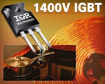
The International Rectifier IRG7PK35UD1 IGBT is optimized for home-appliance applications and is housed in a standard through-hole TO-247 package to keep costs down and simplify installation use on PC boards.
In addition to the 1400-V rating, this IGBT supports 40A continuous collector current and switching speeds from 8 to 30kHz, which is very fast for an IGBT. Due to the voltage, current, and maximum dissipation rating of 167W, it is housed in an industry-standard TO-247 package. The width of each of the three package leads is a little over 1 mm while the minimum lead separation is about 5 mm, commensurate with the 1400V/40A rating (Fig. 5).
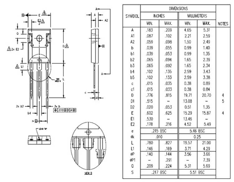
The TO-247 dimensional drawing shows how it must adhere to creepage and clearance mandates for the rated IGBT voltages while handling double-digit currents. (Source: International Rectifier)
The choice of high-voltage IGBT versus MOSFET for applications where they are both viable candidates now has an added dimension: the commercial availability of MOSFETs based on silicon carbide (SiC) rather than traditional silicon alone. In a SiC device, the wider band-gap and other detailed physics result in breakdown voltages that can be 10 times higher than for silicon. The result is that it is possible to fabricate SiC MOSFETs that are much thinner and smaller, and capable of carrying more current with fewer losses, despite other limitations within the SiC device. Further, SiC has a much higher thermal conductivity compared to silicon, resulting in superior power densities. For the critical maximum operating temperature parameter, SiC devices can run at a junction temperature of more than 150°C, reducing system-level heat sink and packaging costs.
Cree offers the C2M family of 1220V and 1700V SiC MOSFETs, also in TO-247 packages, which illustrate this shift. The C2M0160120D is rated to 1.2kV at 17.7A, with just 160mΩ RDS(on), and has a 125W power-dissipation rating; their C2M0160120D is also a 1.2kV device, but for currents up to 90A, with just 25mΩ RDS(on), and a maximum dissipation rating of 463W. This family is well-suited for solar inverters, high-voltage DC/DC converters, motor drives, switch-mode power supply (SMPS), and uninterruptible power-supply (UPS) designs. Cree claims that their SiC MOSFETS have three times the power density of silicon-based IGBTs, and just 20 percent of the losses- both very significant improvements (Fig. 6).
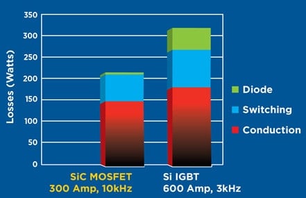
MOSFETS based on silicon carbide offer substantially better high-voltage/high-current efficiency and density than roughly comparable silicon MOSFETs and IGBTs; 300A SiC is more capable than 600A IGBTs (Shown: 250A RMS @ 500V; Source: Cree)
Despite the many challenges of design directly with -- or even just around -- these high voltages, they are an unavoidable, essential aspect of many products. That's why it is important for engineers to be familiar with the associated design aspects and basic high-voltage-related issues, as well as safety and regulatory concerns, to develop a proper perspective along with respect for what high voltages can do and why they are needed.
About Author
Bill Schweber is an electronics engineer who has written three textbooks on electronic communications systems, as well as hundreds of technical articles, opinion columns, and product features. In past roles, he worked as a technical web-site manager for multiple topic-specific sites for EE Times, as well as both the Executive Editor and Analog Editor at EDN. He has been on both sides of the technical PR function, presenting company products, stories, and messages to the media and also as the recipient of these.
He has an MSEE (Univ. of Mass) and BSEE (Columbia Univ.), is a Registered Professional Engineer, and holds an Advanced Class amateur radio license. Bill has also planned, written, and presented on-line courses on a variety of engineering topics, including MOSFET basics, ADC selection, and driving LEDs.
Original source: Mouser


