
555 timer circuits
|
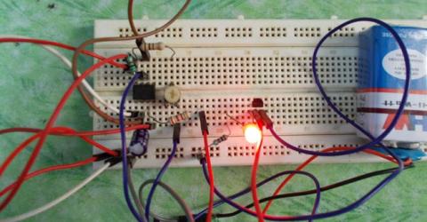
Transistor Tester using 555 Timer IC In electronics most commonly failed component is transistor. To test the working of the transistor, one must go through a lot of testing though multimeter. By testing one terminal after another, this consumes a lot of time and also this option is no good for newbies. The transistor testing circuits which are present already are complex to understand and design. In this… |
|
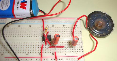
Tic Tic Sound using IC 555 This is a 555 timer IC based fun circuit which generates a sound of loud clicking clock. It is quite simple circuit designed by wiring the 555 IC in astable mode. Components Required 555 Timer IC Capacitors - 2x 10µF Resistors - 47k ohm … |
|
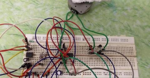
Stepper Motor Driver Circuit Technically stepper motor driver circuit is a Decade Binary Counter circuit. The advantage of this circuit is, it can be used to drive stepper motors having 2-10 steps. Before going any further, let’s discuss more about the basics of a stepper motor. Table of Contents What is a Stepper Motor Driver Circuit? └ Key Benefits… |
|
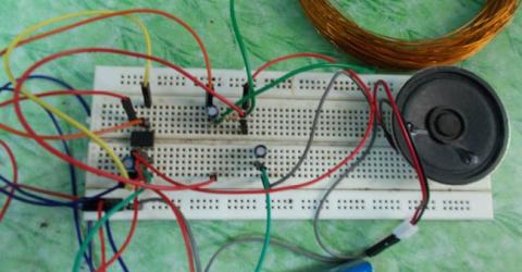
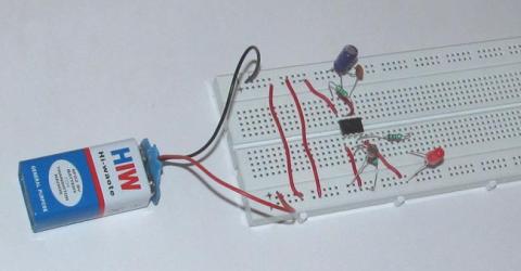
Simple Metal Detector Circuit You can find a metal detector at airports, theaters and various other public places. They are used for the safety of people to detect anyone carrying a metal (Arms etc). In this project we are going to design a simple metal detector circuit. There are so many metal detector designs but most of them are complex in design so here we are going to design a simple… |
|
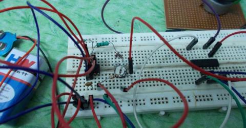
Simple LDR Circuit Here we have explained a dark detector circuit by using 555 timer IC and a LDR (Light Dependent Resistor) which senses the light in surroundings and if it does not find the light, it triggers the IC and glows an LED attached with the circuit. In place of LED we can also use a buzzer or speaker to use it as dark detector alarm. The concept of this LDR circuit is quite simple… |
|
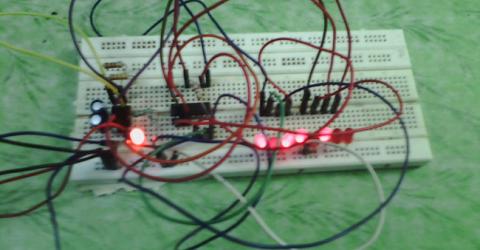
DC Motor Speed Control Circuit The DC MOTOR SPEED CONTROL circuit is primarily a 555 IC based PWM (Pulse Width Modulation) circuit developed to get variable voltage over constant voltage. The method of PWM is explained here. Consider a simple circuit as shown in figure below. If the button is pressed if the figure, then the motor will start rotating and… |
|
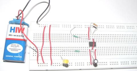
555 Timer Based Binary Counter For an electronics hobbyist or a student 555 timer IC is one of the most important electronic components because of its functioning flexibility. One can develop different kinds of circuits using this IC. Here we are discussing a simple circuit using 555 timer IC as an ASTABLE MULTIVIBRATOR. This circuit make an LED blink for every half second, and the square wave… |
|
Simple Flashing LED using 555 Timer IC While getting started with electronics, you would like to make some simple circuits like a LED circuit to get acquainted with basic circuit designing concepts. Here is one 555 timer based circuit for you – An LED Flasher Circuit Diagram. Using some common easily available electronic components and an easy to understand schematic, this tutorial will show you how to make an LED glow and… |
|
1 Watt LED Dimmer Circuit The LED DIMMER is primarily a 555 IC based PWM (Pulse Width Modulation) circuit developed to get variable voltage over constant voltage. The method of PWM is explained below. Before we get start building a 1 Watt LED Dimmer circuit, first consider a simple circuit as shown in figure below. Now if the switch in the… |

|
Simple Touch Switch Circuit using 555 Timer IC This simple Touch Switch is developed by using 555 timer IC operated as a MONOSTABLE vibrator. Here the stable stage is LOW, so the timer outputs low after the trigger is removed. Basically in this circuit we will have a LED which turns ON when we touch a pin of timer. The LED will be ON for the time during which the trigger is present. Once the trigger is removed the… |
|
Dark Detector using LDR and 555 Timer IC Darkness detector is simply a LDR (Light Dependent Resistor) interfaced square wave generator. In this project the square wave generator is developed as a 555 Timer IC based ASTABLE MULTIVIBRATOR. As this circuit is primarily based on the working principle of LDR, before going any further to understand this LDR circuit, we must get the basic details of the LDR. The figure… |