This simple Touch Switch is developed by using 555 timer IC operated as a MONOSTABLE vibrator. Here the stable stage is LOW, so the timer outputs low after the trigger is removed. Basically in this circuit we will have a LED which turns ON when we touch a pin of timer. The LED will be ON for the time during which the trigger is present. Once the trigger is removed the LED turns OFF.
Circuit Components
- +4 to +6 supply voltage
- 555 IC
- 470Ω, 100KΩ resistors
- 10µF, 100nF (104) capacitors
- LED
- Touch plates
Circuit Diagram
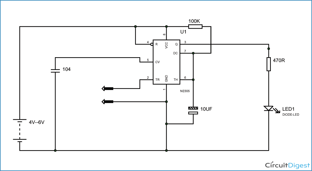
The aove figure shows the circuit diagram of touch switch.
The voltage supplied in this circuit must not exceed 6V, doing so will result in IC burn out. The capacitor between pin6 and pin1 determines the turn on time of LED once a trigger is passed. This circuit can be modified to turn ON for 2minutes for a single trigger by replacing the 10uF capacitance with a 1000uF one. So with the capacitance change one can get many turn on times and so can make the use of this circuit as a stair case lamp.
Working
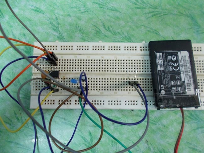
As shown in the below video, the touch switch circuit is connected on the breadboard as per the schematic diagram, and power is turned ON. Now the LED will not turn on as the trigger is not given. The trigger pin in the timer is a high impedance one and is very sensitive. This pin can merely be pulled high by human body potential. This trigger determines the output of 555. This trigger pin SETS the flip-flop inside the 555 TIMER. When this pin is high the output will be high and when this pin is low the output is low. As said earlier since this pin is very sensitive it will pull the 555 output high by touch.
So on touch the trigger pin forces the internal flip-flop to SET mode and so the output goes high. However this high stage can’t be retained for long once the trigger is removed. Once the touch is removed the high stage of output merely depends on the charging time of the capacitor connected between pin6 and pin1.
The capacitor, once reaches a voltage level it discharges through the THRESHOLD pin (pin6) of 555. The trick is, the Threshold pin is set up internally to reset the flip-flop. So on capacitor discharge the threshold pin goes high resetting the flip-flop which is set HIGH by the trigger pin and so the output also goes low with it. Hence the LED turns off at capacitor discharge.
So once the trigger is given the turn on time of the LED depends on the charging time of the capacitor. This turn on time can be increased by connecting a high value capacitor. With enough capacitance this circuit can put up a turn on time of minutes.


can i make a touch circuit using ic 555 with only one touch plate which gets triggered when touched or grounded by object and that should be too sensitive . i saw one circuit that was using ic 555 and a transistor BC547 PN2222A BUT I DID NOT UNDERSTAND THE CIRCUIT SO CAN YOU HELP MEH PLEASE