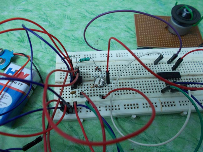
The DC MOTOR SPEED CONTROL circuit is primarily a 555 IC based PWM (Pulse Width Modulation) circuit developed to get variable voltage over constant voltage. The method of PWM is explained here. Consider a simple circuit as shown in figure below.
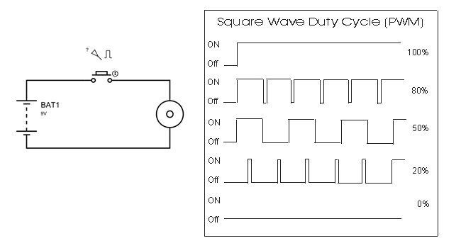
If the button is pressed if the figure, then the motor will start rotating and it will be in motion until the button is pressed. This pressing is continuous and is represented in the first wave of figure. If, for a case, consider button is pressed for 8ms and opened for 2ms over a cycle of 10ms, during this case the motor will not experience the complete 9V battery voltage as the button is pressed only for 8ms, so the RMS terminal voltage across the motor will be around 7V. Due to this reduced RMS voltage the motor will rotate but at a reduced speed. Now the average turn on over a period of 10ms = Turn ON time/ (Turn ON time + Turn OFF time), this is called duty cycle and is of 80% (8/ (8+2)).
In second and third cases the button is pressed even lesser time compared to first case. Because of this, the RMS terminal voltage at the motor terminals gets even decreased further. Due to this reduced voltage the motor speed even decreases further. This decrease in speed with duty cycle continuous to happen until a point, where the motor terminal voltage will not be sufficient to turn the motor.
So by this we can conclude the PWM can be used to vary the motor speed.
Before going further we need to discuss the H-BRIDGE. Now this circuit has mainly two functions, first is to drive a DC motor from low power control signals and the other is to change the direction of rotation of DC motor.
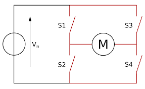
Figure 1
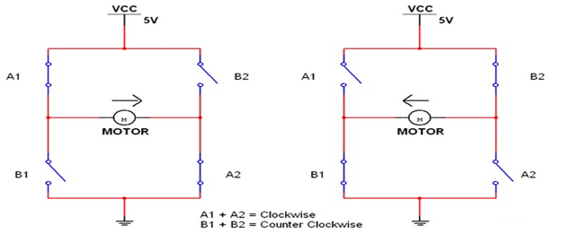
Figure 2
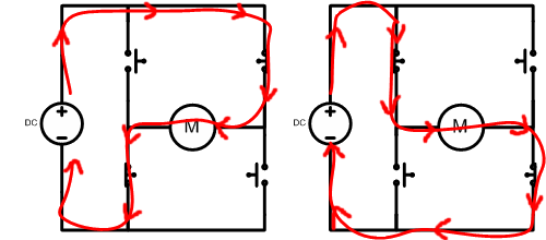
Figure 3
We all know that for a DC motor, to change the direction of rotation, we need to change the polarities of supply voltage of motor. So to change the polarities we use H-bridge. Now in above figure1 we have fours switches. As shown in figure2, for the motor to rotate A1 and A2 are closed. Because of this, current flows through the motor from right to left, as shown in 2nd part of figure3. For now consider the motor rotates clockwise direction. Now if the switches A1 and A2 are opened, B1 and B2 are closed. The current through the motor flows from left to right as shown in 1st part of figure3. This direction of current flow is opposite to the first one and so we see an opposite potential at motor terminal to the first one, so the motor rotates anti clock wise. This is how an H-BRIDGE works. However low power motors can be driven by a H-BRIDGE IC L293D.
L293D is an H-BRIDGE IC designed for driving low power DC motors and is shown in figure. This IC consists two h-bridges and so it can drive two DC motors. So this IC can be used to drive robot's motors from the signals of microcontroller.
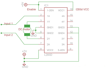
Now as discussed before this IC has ability to change the direction of rotation of DC motor. This is achieved by controlling the voltage levels at INPUT1 and INPUT2.
| Enable Pin | Input Pin 1 | Input Pin 2 | Motor Direction |
| High | Low | High | Turn Right |
| High | High | Low | Turn Left |
| High | Low | Low | Stop |
| High | High | High | Stop |
So as shown in above figure, for clockwise rotation 2A should be high and 1A should be low. Similarly for anti clockwise 1A should be high and 2A should be low.
Circuit Components
- +9v power supply
- Small DC motor
- 555 Timer IC
- 1K, 100R resistors
- L293D IC
- 100K -220K preset or pot
- IN4148 or IN4047 x 2
- 10nF or 22nF capacitor
- Switch
Circuit Diagram
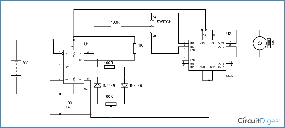
The circuit is connected in breadboard as per the DC motor speed control circuit diagram shown above. The pot here is used to adjust the speed of motor. The switch is to change the direction of rotation of motor. The capacitor here must not of a fixed value; the user can experiment with it for a right one.
Working
When power is supplied, 555 TIMER generates PWM signal with a duty ratio based on the pot resistance ratio. Because of the pot and the diode pair, here the capacitor (which triggers the output) must charge and discharge through a different set of resistance and because of this, the capacitor takes a different time to charge and discharge. Since the output will be high when the capacitor is charging and is low when the capacitor is discharging, we get a difference in high output and low output times, and so the PWM.
This PWM of timer is fed to the signal pin of L239D h-bridge to drive the DC motor. With the varying PWM ratio we get varying RMS terminal voltage and so the speed. To change the direction of rotation the PWM of timer is connected to the second signal pin.
Comments
I connected the circuit as shown in the figure but It is not working can you please help me.
I have used the 10nF capacitor and potentiometer.
Please send application or limitations for DC speed control with pwm IC 555 timer



please send the avr code for speed controll of dc motor using 555 timer and L293D.