
Pulse Width Modulation using 555 timer is an important feature of today’s microcontroller due to its requirement for controlling many devices in almost every field of Electronics. PWM is widely used for motor control, lighting control, etc. Sometimes we do not use a microcontroller in our applications, and if we need to generate PWM without a microcontroller, then we prefer some general-purpose ICs like op-amps, timers, pulse generators, etc. Here we are using a 555 PWM circuit diagram. 555 Timer IC is a very useful and general-purpose IC which can be used in many applications. Understanding PWM using IC 555 opens doors to countless control applications while providing hands-on experience with analog timing circuits and digital control principles.
Table of Contents
Essential Components for 555 PWM Circuit Diagram
Constructing a dependable pulse width modulation circuit using 555 timer requires the right components. After lots of testing and real-world implementation, here are the accepted components listed with specifications:
Component | Value/Type | Quantity | Purpose |
|---|---|---|---|
555 Timer IC | NE555 / LM555 | 1 | Generates a PWM signal |
Variable Resistor | 10kΩ Potentiometer | 1 | Adjusts duty cycle |
Fixed Resistor | 100Ω | 1 | Current limiting in a circuit |
Timing Capacitor | 0.1µF Ceramic | 1 | Sets frequency/timing |
Optional Resistor | 1kΩ | 1 (optional) | Additional timing/LED protection |
Breadboard | Half/Full size | 1 | Circuit assembly platform |
Power Supply | 9V Battery | 1 | Provides circuit power |
Battery Connector | Clip for 9V battery | 1 | Connect the battery to the breadboard |
LED Indicator | 5mm Red LED | 1 | Visual PWM signal output |
Multimeter / CRO | Digital multimeter / Oscilloscope | 1 | For testing and measuring PWM |
Jumper Wires | Various lengths | As required | Circuit connections |
How PWM Using IC 555 Works: Technical Explanation
Pulse Width Modulation (PWM) is a digital signal which is most commonly used in control circuitry. This signal is set high (5V) and low (0V) in a predefined time and speed. The time during which the signal stays high is called the “on time,” and the time during which the signal stays low is called the “off time”. There are two important parameters for a PWM as discussed below:
Duty Cycle Control in 555 Pulse Width Modulation Circuit
In our enhanced pulse width modulation using IC 555 design, the percentage of time in which the PWM signal remains HIGH (on time) is called as duty cycle. If the signal is always ON, it is in a 100% duty cycle, and if it is always off, it is 0% duty cycle.
Duty Cycle =Turn ON time/ (Turn ON time + Turn OFF time)
Frequency Calculation for Pulse Width Modulation Using IC 555
The frequency of a PWM signal determines how fast a PWM completes one period. One Period is complete ON and OFF of a PWM signal as shown in the above figure. In our tutorial, we will set a frequency of 5KHz. The output frequency of our PWM using IC 555 circuit is determined by the total timing period.
We can notice if the LED is OFF for half a second and the LED is ON for the other half second. But if the Frequency of ON and OFF times increased from ‘1 per second’ to ’50 per second’. The human eye cannot capture this frequency. For a normal eye, the LED will be seen as glowing with half of its brightness. So with further reduction of ON time the LED appears much lighter.
We have previously used PWM in many of our projects. Check them below:
- Pulse Width Modulation with ATmega32
- PWM with Arduino Uno
- Generating PWM using PIC Microcontroller
- Raspberry Pi PWM Tutorial
- DC Motor Control with Raspberry Pi
- 1-watt LED Dimmer
- Arduino-Based LED Dimmer using PWM
Complete 555 Timer PWM Generator Circuit Diagram and Assembly
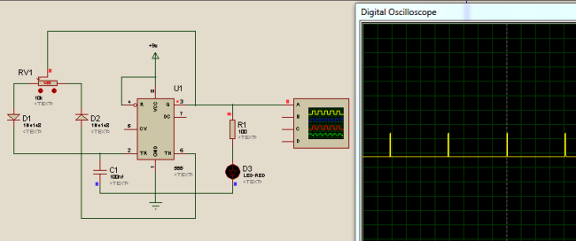
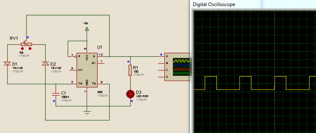
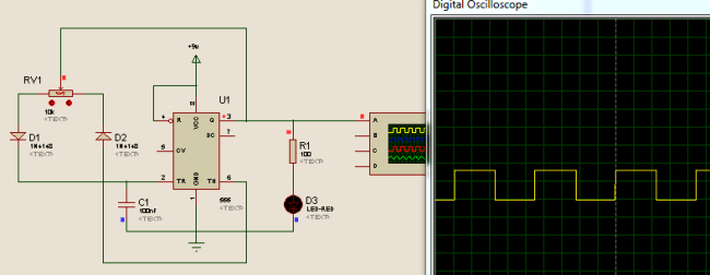
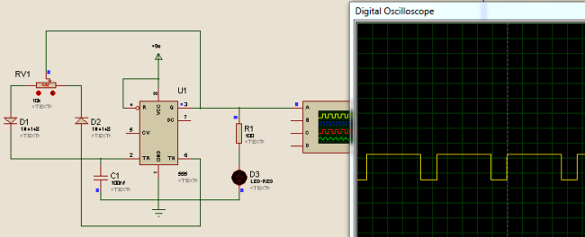
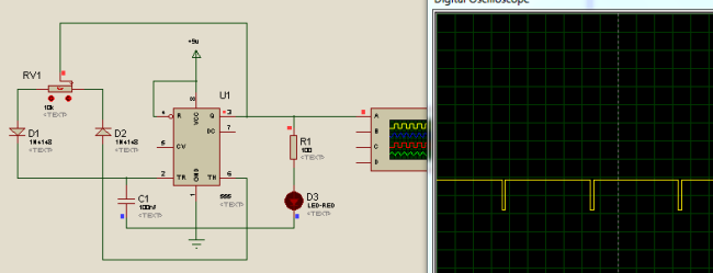
The 555 PWM circuit diagram shown below is the overall schematic with diode steering for full duty cycle control. This design has been safely used to condition over a variety of loads and has proven to deliver stable PWM generation.

In this PWM generator circuit, as we mentioned above, we have used a 555 Timer IC for generating a PWM signal. Here, we have controlled the output frequency of the PWM signal by selecting resistor RV1 and capacitor C1. We have used a variable resistor in place of a fixed resistor to change the duty cycle of the output signal. Capacitor charging through D1 diode and Discharge through D2 diode will generate a PWM signal at the 555 timer's output pin.
The formula below is used for deriving the frequency of the PWM signal:
F = 0.693*RV1*C1
The whole working and demonstration of PWM generation is given in the Video at the end, where you can find the PWM effect on the LED and can check it on the Multimeter.
⇢ Pin 8 (VCC) connects to the +9V supply
⇢ Pin 1 (GND) and Pin 5 (Control) connect to ground with a 0.01µF bypass capacitor
⇢Pin 4 (Reset) connects to VCC for proper operation
⇢ Pins 2 (Trigger) and 6 (⇢Threshold) connect to the timing network
⇢Pin 7 (Discharge) connects through steering diodes to the timing resistors
⇢ Pin 3 (Output) provides the PWM
Pulse Width Modulation Circuit Using 555 Timer: Step-by-Step Build Guide
Below are some Snapshots:
Assembly Instructions
Step | Action |
|---|---|
Power Rail Setup | Establish +9V and ground rails on the breadboard. |
IC Placement | Insert the 555 timer IC across the center gap. |
Power Connections | Connect Pin 8 to +9V and Pin 1 to ground. |
Reset and Control | Connect Pin 4 to +9V; connect Pin 5 to ground via a 0.01 µF capacitor. |
Timing Network | Install diodes D1 and D2 with correct polarity. |
Potentiometer | Wire a 10 kΩ potentiometer for duty cycle control. |
Capacitor | Connect a 0.1 µF timing capacitor. |
Output Circuit | Add an LED with a current-limiting resistor. |
Final Connections | Link Pins 2 and 6 to the timing junction. |
Testing | Apply power and verify PWM output with a multimeter. |
Practical Applications with the 555 Pulse Width Modulation Circuit
Our 555 PWM design is used in many practical situations:
Proven Applications:
» LED Dimmer: Smooth variable brightness for lighting projects.
» DC Motor Speed Control: Variable speed drives for small motors.
» Heating Element Control: Control temperature by controlling the power.
» Audio Tone Generation: Variable duty cycle square wave sounds.
» Power Supply Control: Switching regulator control circuitry.
» Servo Positioning: PWM signals for hobby servos.
» Battery Charger Control: Controlled charging current.
» MOSFET Gate Driver: Power switching applications.
Advantages Over Microcontroller PWM
- No programming required
- Instantaneous analog adjustment
- Low cost for simple applications
- Highly reliable and simple
- Has an educational aspect in comprehending PWM principles
Frequently Asked Questions: PWM using IC 555
⇥ How does the IC 555 timer PWM work?
The 555 timer produces PWM through charging and discharging a capacitor via various paths of resistance. The duty cycle is adjusted by varying the ratio of resistance, but frequency varies with the RC time constant. This generates variable pulse widths at a constant frequency.
⇥ What is the range of duty cycle for the 555 pulse width modulation circuit?
A typical 555 PWM circuit can provide duty cycles between 10% and 90%. With diode steering modification, it is possible to obtain about 0% to 100% duty cycle control using distinct charging and discharging circuits through different resistors.
⇥ Which components are mandatory for a 555 PWM circuit diagram design?
Fundamental components are: 555 timer IC, timing capacitor (0.1µF), variable resistor (10kΩ potentiometer), fixed resistor (1kΩ), power supply (5-15V), and steering diodes for duty cycle control. Optional components include an LED for visual feedback.
⇥ What is the maximum frequency of a pulse width modulation using 555 timer?
The 555 timer would support PWM frequencies up to about 500kHz; however, typical values would be put at about 100kHz for stable operation. Frequencies greater than that may introduce timing errors because of internal delays and turn around times of the IC.
⇥ Why use diodes on PWM with an IC 555 configuration?
Diodes provide separate charging and discharging paths for the timing capacitor. This allows for independent control of ON time and OFF time, allowing duty cycle control from nearly 0% to 100%, which you cannot do with conventional 555 astable operation.
⇥ Can a 555 pulse width modulation circuit directly power motors?
No, the 555 timer output (≤200mA) can not power motors. Use the PWM signal to drive a MOSFET or transistor driver circuit capable of supplying motor current demands. This provides good isolation, correct current drive, and safe operation.
Conclusion
This guide to pulse width modulation using 555 timer covers the theory of pulse width modulation as well as the application of the theory through a tested circuit. The circuit is designed to work properly in a variety of applications. As you pursue your experiments into the fundamentals of PWM or the design of control systems, you can use this 555 PWM circuit diagram as an excellent starting point.
If you are designing advanced applications, you can make use of this PWM generator with operational amplifiers for a better output drive, or you can cascade (connect in a series) multiple 555 timer chips for multi-phase PWM. The ideas you have learned in this chapter apply to physical systems that involve PWM and micro-controllers.
Related 555 Timer Projects
Take on the versatility of the 555 timer IC with these hand-picked projects and resources. From generating precise PWM signals to controlling LED brightness and DC motor speeds, these circuits deepen your understanding of timing, modulation, and practical electronics design. Explore tutorials and calculators that make building and customizing your 555 timer applications easier and more insightful.

What is PWM: Pulse Width Modulation
PWM is used to produce Analog signals from a digital device like microcontroller. In this article we will learn about what is PWM, PWM signals and some parameters associated with it so that we will be confident in using them in our designs.

555 Timer based Buck Regulator
In this article, we will make a buck converter using 555 timer IC and a IRFZ44N N channel MOSFET and use it as LED dimmer circuit or as a motor speed controller circuit.

555 Timer Astable Circuit Calculator
Use this 555 timer calculator to calculate the frequency, period and duty cycle for a 555 timer astable circuit.
Comments
It’s helpful thank you very much!
what is the input to pin 5
At LAST! I've been searching for an explanation of PWM and a circuit for it using a 555 timer. I've found lots of circuits!--but they all seemed to be based, at least in part, on the OPINION of the author. So you can imagine my elation to have run across your site, and the specific circuit I sought. Totally professional, totally clear, and totally TRUSTED!
You are what futurists 30 years ago predicted the Internet would do to improve civilization.
Thank you,
Bruce Ratcliffe, humble Electronics Teacher, Fresno, California
I don't see how F=.693 * RV1 * C1 works out to 5 kHz with the values shown for this article. RV1 is 10,000 and C1 is 100 nF (1E-7 farad).

Can i Generate 7mhz or 3.5mhz pwm signal on 50%duty cycle?
i am not able to generate this much pwm signal to the arduino .
and in your mind having some external ic is there to produced the 7mhz pwm signal then tell me.