

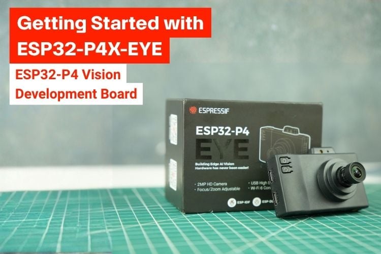
Vision development boards are useful when an embedded project needs to combine image capture, local display, audio input, storage and wireless connectivity in a single platform. The ESP32-P4X-EYE takes this approach around the ESP32-P4, adding an ESP32-C6 wireless module, a 2MP MIPI-CSI camera, a 1.54-inch SPI LCD, a digital microphone, MicroSD storage, USB interfaces and a 2 × 10-pin expansion header.
Espressif positions the ESP32-P4X-EYE mainly for camera applications such as smart surveillance, vision-model detection and IoT edge computing. The board is also designed as a practical development platform, with a USB debug interface for programming, a dedicated USB 2.0 device interface, user buttons, a rotary encoder, fill light and a battery connector.
In this guide, we look at the hardware in detail, explain the major interfaces and power options, go through the boot and firmware-download process, and show how to build and flash Espressif's Factory Demo using ESP-IDF. The Factory Demo brings together camera capture, video recording, storage, USB mass-storage access and several AI detection features.
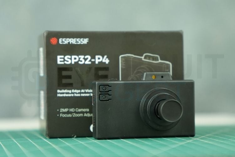
Key Features of the ESP32-P4X-EYE
The ESP32-P4X-EYE is built around the ESP32-P4 and uses the ESP32-C6-MINI-1U as its wireless controller. The board includes 16 MB of SPI flash, and the ESP32-P4 platform supports up to 32 MB of PSRAM. Its peripheral set is centered on imaging: the camera connects through MIPI-CSI, while the LCD uses SPI.
| Specification |
Parameter |
| Main Controller |
ESP32-P4, dual-core RISC-V processor |
| Wireless Controller |
ESP32-C6-MINI-1U for Wi-Fi and Bluetooth |
| SPI Flash |
16 MB |
| PSRAM |
Up to 32 MB |
| Camera |
2 MP MIPI-CSI camera, manually adjustable focal length |
| Display |
1.54-inch, 240 × 240 LCD, SPI; ST7789 |
| MicroSD |
1-bit / 4-bit SD bus; SDIO or SPI |
| USB Device |
USB 2.0 High-Speed OTG device interface |
| USB Debug |
USB-Serial-JTAG interface; power, flashing and debugging |
| Microphone |
Digital microphone, PDM interface |
| Controls |
Rotary encoder, three user-defined buttons, Boot and Reset buttons |
| Lighting |
White fill light for image capture and video |
| Expansion |
2 × 10P female header |
| Battery |
Lithium battery connector; maximum 4 × 25 × 45 mm |
ESP32-P4X-EYE Applications and Use Cases
The board is primarily intended for applications that need real-time image processing together with wireless communication. Espressif lists smart surveillance cameras, vision-model detection and IoT edge computing among the target applications. The combination of MIPI-CSI, a local display, MicroSD storage, USB High-Speed and the ESP32-C6 wireless module also makes the platform suitable for prototyping connected camera products.
ESP32-P4X-EYE Development Board: Physical Overview
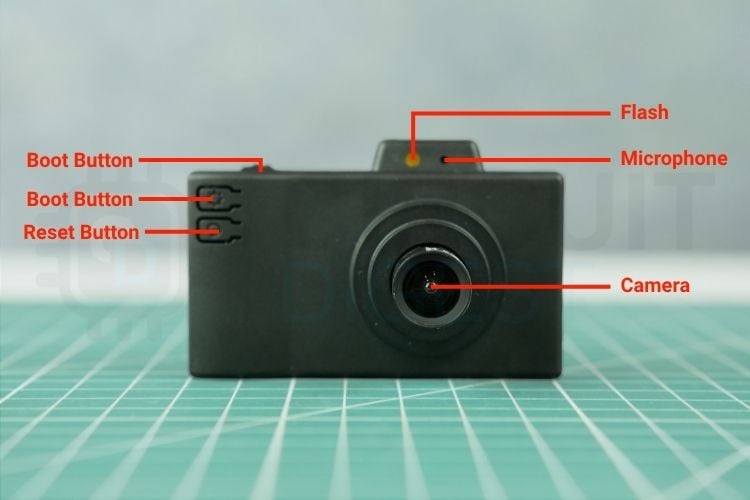
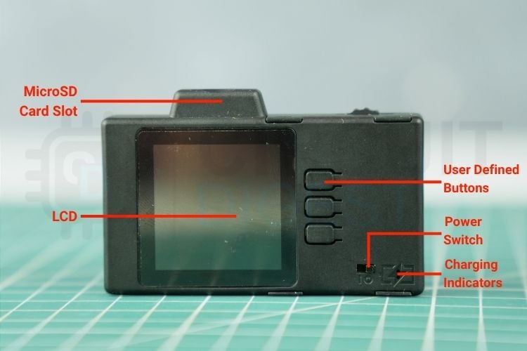
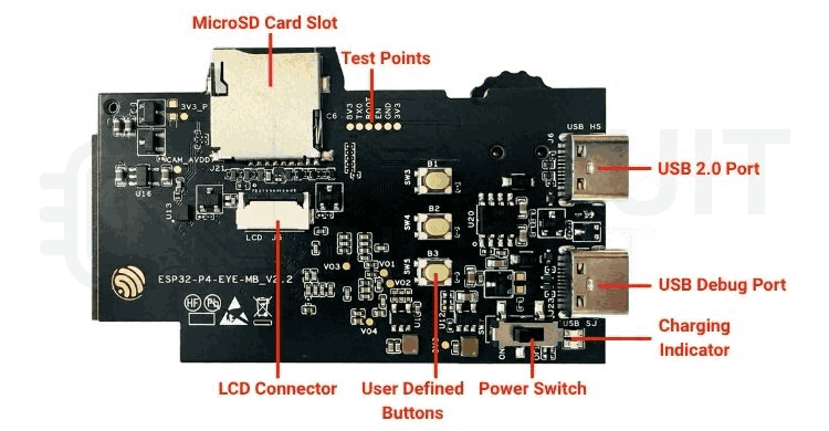
The ESP32-P4X-EYE uses an enclosed form factor with the LCD and user controls on the front, while the camera, fill light, microphone and expansion header are positioned around the opposite side. The PCB exposes the MicroSD slot, USB connectors, user buttons and power switch so that the board can be used without removing the enclosure.
Front and Side Interfaces
The front-facing assembly includes the 1.54-inch LCD, the MicroSD card slot and three user-defined buttons. Two USB-C connectors are provided on the side: the USB 2.0 Device Port is the high-speed USB interface and can also power the board, while the USB Debug Port is intended for programming, debugging and power.
Rear Hardware
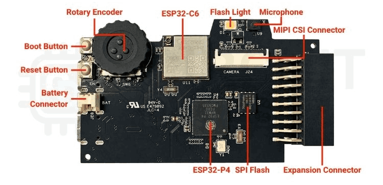
The opposite side of the board carries the ESP32-P4, ESP32-C6-MINI-1U, SPI flash, battery connector, MIPI-CSI camera connector, digital microphone, fill light, rotary encoder and the 2 × 10P female header. The Boot and Reset buttons are also located on this side of the board.
What's Inside the ESP32-P4X-EYE
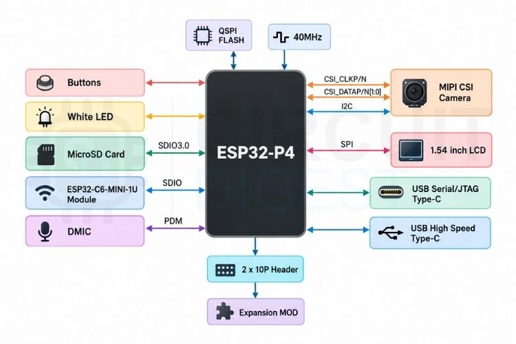
The functional block diagram shows the ESP32-P4 at the center of the board. The processor connects to the MIPI-CSI camera through dedicated CSI lanes and I²C control, to the 1.54-inch LCD through SPI, and to the MicroSD card through SDIO. The ESP32-C6-MINI-1U communicates with the ESP32-P4 through SDIO, while the digital microphone uses PDM. USB High-Speed and USB-Serial-JTAG provide the two USB paths.
ESP32-P4 Main Controller
At the center of the board is the ESP32-P4, a dual-core RISC-V processor designed for high-performance embedded workloads. Espressif highlights USB 2.0, MIPI-CSI/DSI, H.264 encoding and a broad peripheral set as part of the ESP32-P4 platform. On the ESP32-P4X-EYE, the processor handles the camera, LCD, MicroSD, USB, microphone and expansion interfaces.
| Parameter | Specification |
| Processor | ESP32-P4 |
| CPU Architecture | Dual-core RISC-V |
| PSRAM | Up to 32 MB |
| Board Flash | 16 MB SPI flash |
| Camera Interface | MIPI-CSI |
| Display Interface | SPI |
| USB | USB 2.0 High-Speed + USB-Serial-JTAG |
| Memory / Storage | 16 MB flash + external MicroSD |
ESP32-C6 Wireless Controller
Wireless connectivity is provided by the ESP32-C6-MINI-1U module. It serves as the board's Wi-Fi and Bluetooth communication module and is connected to the ESP32-P4 through an SDIO link. The module is placed on the rear PCB alongside the ESP32-P4 and other high-speed peripherals.
| Parameter | Specification |
| Module | ESP32-C6-MINI-1U |
| Function | Wi-Fi and Bluetooth communication |
| Host Connection | SDIO to ESP32-P4 |
Camera
The camera is one of the main features of the ESP32-P4X-EYE. The user guide specifies a 2 MP camera with manually adjustable focal length and a MIPI-CSI connection to the ESP32-P4. The related Espressif camera documentation identifies an OV2710 overview, while the Factory Demo log detects the sensor with PID 0x2710.
| Parameter | Specification |
| Resolution | 2 MP |
| Interface | MIPI-CSI |
| Focal Length | Manually adjustable |
| Sensor Reference | OV2710 overview is linked by Espressif |
| Factory Demo Detection | OV2710, PID 0x2710 |
1.54-inch LCD
The board includes a 1.54-inch, 240 × 240 SPI LCD. The user guide identifies the display controller as ST7789 and specifies GPIO20 as the LCD_BL backlight-control pin. The display is used by the Factory Demo to provide the camera preview and user interface.
| Parameter | Specification |
| Display Size | 1.54 inch |
| Resolution | 240 × 240 pixels |
| Interface | SPI |
| Controller | ST7789 |
| Backlight | LCD_BL, GPIO20 |
Digital Microphone and Audio
A digital microphone is integrated on the board for voice and audio capture. The functional block diagram shows the microphone connected to the ESP32-P4 through a PDM interface. Espressif lists voice recognition and audio recording as example uses for the digital microphone.
| Parameter | Specification |
| Microphone | Digital microphone |
| Interface | PDM |
| Applications | Voice recognition and audio recording |
MicroSD Card Storage
The MicroSD card slot supports both SDIO and SPI communication. The official hardware guide specifies 1-bit and 4-bit SD bus configurations. This makes the slot useful for storing captured photographs and video files generated by the Factory Demo.
| Parameter | Specification |
| Card Interface | MicroSD |
| SD Bus | 1-bit and 4-bit |
| Protocols | SDIO or SPI |
| Factory Demo Photo Folder | esp32_p4_pic_save |
| Factory Demo Video Folder | esp32_p4_mp4_save |
USB Interfaces
The ESP32-P4X-EYE has two USB-C connectors with different roles. The USB 2.0 Device Port is connected to the ESP32-P4 USB 2.0 High-Speed OTG interface and can also power the board. The USB Debug Port connects to the ESP32-P4 USB-Serial-JTAG interface and is the recommended connector for firmware flashing and debugging.
| Connector | Function |
| USB 2.0 Device Port | USB 2.0 High-Speed device interface; can power the board |
| USB Debug Port | Power, firmware flashing, debugging and USB-Serial-JTAG |
Buttons, Rotary Encoder and Fill Light
Three user-defined buttons are available for application control. A rotary encoder provides both rotational input and a push action, allowing applications to implement menu navigation, parameter adjustment or camera zoom control. The board also has dedicated Boot and Reset buttons. A white fill light provides illumination for image capture and video recording.
| Component | Function |
| User-defined Buttons | Application-specific input |
| Rotary Encoder | Application input; can control menus or camera zoom |
| Boot Button | Selects firmware download mode when used with Reset |
| Reset Button | Resets the ESP32-P4 |
| White Fill Light | Illumination for image capture and video |
Power Supply and Battery
The ESP32-P4X-EYE can be powered through either USB-C connector. Espressif recommends the USB Debug Port for flashing and debugging, but both the USB 2.0 Device Port and USB Debug Port can provide board power. If a lithium battery is installed, powering the board through USB also charges the battery.
The battery connector is located on the PCB and is accessible after opening the enclosure. The official guide specifies a lithium battery no larger than 4 mm × 25 mm × 45 mm, using a 1.25 mm pitch connector with polarity matching the PCB markings. The charging indicator is red while charging and turns green when charging is complete.
2 × 10P Expansion Header
Most of the ESP32-P4X-EYE I/O is exposed through a 2 × 10P expansion header. The official header illustration shows power, ground, I²C and multiple general-purpose GPIOs. The header is intended for jumper-wire connections and custom expansion hardware.
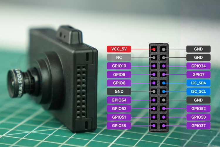
| Row | Left Pin | Right Pin |
| 1 | VCC_5V | GND |
| 2 | NC | GND |
| 3 | GPIO10 | GPIO34 |
| 4 | GPIO8 | GPIO7 |
| 5 | GPIO6 | I2C_SDA |
| 6 | GND | I2C_SCL |
| 7 | GPIO54 | GND |
| 8 | GPIO53 | GPIO52 |
| 9 | GPIO51 | GPIO50 |
| 10 | GPIO38 | GPIO37 |
ESP32-P4X-EYE Factory Demo
The easiest way to start with the ESP32-P4X-EYE is to power the board, load Espressif’s Factory Demo, and verify the camera, LCD, storage, buttons and USB interfaces before moving to a custom application. The USB Debug Port is the preferred connection for programming and serial monitoring.
First Power-Up
1. Inspect the board and enclosure for visible damage.
2. Insert a MicroSD card if you want to test photo, timed-capture or video functions.
3. Connect a known-good USB-C data cable to the USB Debug Port.
4. Move the power switch to the ON position when using the board’s normal 5 V input path.
5. Use the Reset button if the application needs to be restarted.
Using the Factory Demo
The Factory Demo provides a practical test of the complete hardware stack. Photo capture, timed capture and video recording use the camera and MicroSD card; the LCD provides the local user interface; the rotary encoder and buttons provide control; and the USB 2.0 Device port can expose the SD card to a host computer.
Camera, Storage and AI Features
Photo capture stores images in the esp32_p4_pic_save directory on the SD card. Timed capture uses the same directory. Video recording stores MP4 files in esp32_p4_mp4_save. The AI modes provide face and pedestrian detection, while YOLOv11-nano object detection can be enabled from the settings.
USB SD-Card Access
When the Factory Demo enables USB mass-storage support, connect the USB 2.0 Device port to a host computer to access the SD-card storage. This is separate from the USB Debug Port used for flashing and serial debugging.
Battery Operation
The board can also operate from a lithium battery connected to the internal battery connector. Follow the connector polarity marking and the battery size limits specified by Espressif. When external USB power is applied with a battery installed, the battery charging circuit can operate simultaneously.
The Factory Demo is Espressif's reference application for the ESP32-P4X-EYE. It combines the camera, SPI LCD, USB High-Speed interface, buttons, rotary encoder and SD-card storage into a small camera application. The official example is developed for ESP-IDF release/v5.5 and its bugfix releases.
| Feature | What It Does |
| Photo Capture | Captures photographs; digital zoom can be controlled with the rotary encoder or buttons. SD card required. |
| Timed Capture | Captures photographs at a selected interval; any button stops the mode. SD card required. |
| Video Recording | Records video to MP4; SD card required. Files are stored in esp32_p4_mp4_save. |
| AI Detection | Provides face detection and pedestrian detection using the esp-dl inference framework. |
| Album | Browses captured photographs and allows the current photo to be deleted with the encoder button. |
| USB Mounting | Exposes SD-card files to a PC through the USB 2.0 Device interface. |
| Settings | Controls rotation, YOLO detection, image resolution, flash, saturation, contrast, brightness and hue. |
| YOLO Object Detection | Can analyse photos while browsing the album when enabled in settings. |
Using the Factory Demo
With an SD card installed, the photo and timed-capture modes save images in the esp32_p4_pic_save directory. Video recordings are stored as MP4 files in esp32_p4_mp4_save. The album can be used to review photographs, while USB mounting allows the SD-card contents to be accessed directly from a computer through the USB 2.0 Device Port.
The AI detection mode provides face and pedestrian detection and uses the esp-dl inference framework. The Factory Demo also includes YOLOv11-nano-based object detection; when enabled, object detection can be performed on photographs as they are browsed in the album.
Getting Started with ESP-IDF
Espressif recommends using a good-quality USB cable because charge-only cables may not provide the data lines required for programming. A computer running Windows, Linux or macOS, the ESP32-P4X-EYE and a USB cable are the minimum hardware required. A MicroSD card and lithium battery are optional. You can refer to the official ESP-IDF document to know more about its installation and setup.
| Requirement |
Details |
| Development Board |
ESP32-P4X-EYE |
| USB Cable |
Data-capable USB-C cable |
| Computer |
Windows, Linux or macOS |
| Optional |
MicroSD card and lithium battery |
| Recommended USB Port |
USB Debug Port for flashing and debugging |
| ESP-IDF |
Release/v5.5 and bugfix releases for the Factory Demo |
Clone the Espressif Development-Kits Repository
The Factory Demo is maintained in Espressif's esp-dev-kits repository. Clone the repository recursively so that its required components are also available.
git clone --recursive https://github.com/espressif/esp-dev-kits.gitConfigure the Board Support Package
Open the Factory Demo project with ESP-IDF and run menuconfig. In the configuration menu, select the Board Support Package section and configure the ESP32-P4X-EYE board as required by the project. Espressif notes that the ESP32P4_SELECTS_REV_LESS_V3 option is for the original ESP32-P4 chip; the ESP32-P4X-EYE uses the upgraded ESP32-P4 revision v3.1 or later.
Build and Flash the Factory Demo
Connect the USB Debug Port to the computer. If the board is not already in download mode, hold the Boot button and press the Reset button to reset the ESP32-P4 and enter firmware download mode. Firmware can then be downloaded to the SPI flash through the USB Debug Port.
idf.py -p PORT flash monitorReplace PORT with the serial-port name assigned to the board. The same command builds, flashes and opens the serial monitor when the project is configured for the board. Press Ctrl-] to exit the serial monitor.
Hardware Revision
The ESP32-P4X-EYE is the successor to the ESP32-P4-EYE in terms of the main-chip revision. Espressif states that the main chip on the ESP32-P4X-EYE has been upgraded to ESP32-P4 chip revision v3.1 or later. This distinction is important when selecting firmware or examples: Espressif's examples repository contains firmware files with p4x_ prefixes for ESP32-P4X boards, while p4_ prefixes are used for the original ESP32-P4 boards.
Conclusion
The ESP32-P4X-EYE is a compact vision-focused development platform that brings together the ESP32-P4's high-performance processing with MIPI-CSI imaging, a local SPI display, MicroSD storage, digital audio input, USB High-Speed connectivity and ESP32-C6 wireless communication. Its 2 × 10P header also leaves a useful set of GPIOs available for custom hardware.
The Factory Demo is a useful starting point because it exercises most of the board's major peripherals in one application. Once the camera, display, storage and USB paths are working, developers can use the same ESP-IDF environment to build more specialized vision, monitoring and edge-computing applications. For more details, you can refer to the official ESP32-P4X-EYE User Guide.
Sample Code GitHub Repository
We have created an ESP-IDF security-camera firmware for the ESP32-P4X-EYE that detects faces, records short MJPEG video clips with AAC audio as MP4 files, and saves them to the microSD card. The firmware also provides live preview, face detection, on-device video playback, USB SD-card access, and configurable recording settings.



Add a comment
No account needed. Your comment appears once a moderator has reviewed it.