


Data logging is one of the most common microcontroller applications. Whether you're monitoring temperature, recording sensor readings, tracking button presses, or collecting other information, storing data for later analysis is essential thing. It can be done locally or using some cloud services as well. You can find a lot of helpful articles in our collection of ESP32 based projects. In this tutorial, we'll build an ESP32 based data logger that records button presses along with their date and time stamps and saves them to a text file on an SD card. We are using the ESP32-S3 CAM Module because it includes an on-board SD Card reader, and we don't want to use an external SD Card reader module.
We have added one more feature to this. Instead of removing the SD card every time we want to access the recorded data, we'll make the ESP32-S3 appear as a USB flash drive when connected to a computer. This allows us to open the log file directly from our laptop. We'll use FAT filesystem support for managing files on the SD card and USB Mass Storage Class (USB MSC) to expose the SD card to the computer, just like how a pendrive appears as a separate drive when we plug it in. We will be using the Native USB port to access the files. There are several other file systems that can be used on an ESP32. One such popular file system is LittleFS. If you’d like to learn more about it, check out the "How to use LittleFS with NodeMCU tutorial".
An ESP32 data logger reads events or sensor values, adds a date and time stamp, and saves each entry to storage. In this build, an ESP32-S3 CAM board logs push-button presses to log.txt on its on-board microSD card and then appears on your computer as a USB flash drive, so you can open the log without removing the card.
- Board: ESP32-S3-WROOM CAM (on-board microSD slot + native USB port)
- Storage: microSD card, FAT32, accessed through
SD_MMCin 1-bit mode - Timestamps: NTP time over Wi-Fi, set to IST (UTC+5:30)
- PC access: USB Mass Storage Class (USB MSC) over the native USB port
- Mode switch: hold the BOOT button for 2 seconds to toggle Logging Mode and USB Drive Mode
Table of Contents
Native USB vs USB-to-UART: Quick Comparison
Several ESP32-S3 boards have a built-in USB OTG port that allows them to communicate directly with USB devices such as computers. Development boards like the ESP32-S3-WROOM CAM expose this through a native USB port, which is connected directly to the ESP32-S3's USB pins rather than going through a separate USB-to-Serial converter. This allows the ESP32-S3 to support USB device functionalities such as USB Mass Storage Class (MSC), which is what we use in this project.

When we connect this native USB port to a laptop, the ESP32-S3 can identify itself as a USB storage device using the USB MSC protocol. The laptop then recognises the SD card as a separate drive, allowing us to access its files just like a regular pen drive. Make sure to use the native USB port rather than the USB-to-UART port, as the latter is primarily intended for programming and serial communication.
Components Required for the ESP32 Data Logger
Let's take a look at the components used in this tutorial. As said above, we are going to demonstrate the ESP32 data logger with a simple push button press.

S No | Item | Description |
| 1 | ESP32-S3-WROOM CAM | The main microcontroller. It has an inbuilt MicroSD card slot and a native USB port. |
| 2 | MicroSD card | To store the logged data |
| 3 | Push Button | To act as a trigger to save data to the MicroSD Card |
| 4 | Wires | Single-stranded wires to make connections |
| 5 | Breadboard | To assemble the whole project |
| 6 | USB Cable | For programming the ESP32 |
ESP32 Data Logger Circuit Diagram
Let's take a look at the circuit diagram for this project. We have the main ESP32-S3 board that is connected to a push button. The push button leads are connected to the ESP32-S3 at GPIO pin 14 and GND.

The circuit diagram as well as the code, is set very basic so that it's easy to learn and understand the working. Instead of the push button, it can be any sensor connected to the required GPIO pin number. We just need to modify the code accordingly. Instead of using a separate push button for switching the modes, we are using the onboard BOOT Button to switch between the modes. It's programmed in such a way that pressing the Boot Button for 2 seconds switches the mode. In the Arduino IDE, under Tools, select the Flash Size as 16 MB or the one that matches your board.
ESP32 Data Logger Programming: Code Explanation
This section walks through the key parts of the ESP32 data logger programming. The complete sketch is linked in the GitHub section at the end.
#include <WiFi.h>
#include <time.h>
#include <Preferences.h>
#include "USB.h"
#include "USBMSC.h"
#include "SD_MMC.h"
Let's see what functions each of the above libraries has.
S No | Library | Purpose |
| 1 | WiFi.h | Connects to Wi-Fi to obtain the current time. |
| 2 | time.h | Handles timestamps and time formatting. |
| 3 | Preferences.h | Stores the selected operating mode in non-volatile memory. |
| 4 | USB.h | Initialises the ESP32-S3's native USB interface. |
| 5 | USBMSC.h | Implements USB Mass Storage Class functionality. |
| 6 | SD_MMC.h | Communicates with the SD card using the SD/MMC interface |
#define SD_CLK_PIN 39
#define SD_CMD_PIN 38
#define SD_D0_PIN  40
#define LED_PIN    48
#define BUTTON_PIN 14
#define MODE_PIN    0
SD_CLK_PIN, SD_CMD_PIN, and SD_D0_PIN configure the SD card. LED_PIN controls the onboard WS2812 RGB LED. BUTTON_PIN is connected to the external push button used for logging. MODE_PIN is connected to the BOOT button and is used to switch between logging and USB drive modes.
void ledColor(uint8_t r, uint8_t g, uint8_t b) {
 neopixelWrite(LED_PIN, r, g, b);
}
void ledOff() {
 neopixelWrite(LED_PIN, 0, 0, 0);
}
Simple helper functions to control the onboard RGB LED. A short blink at startup, Green for button presses, blue for USB drive mode. Red for SD card error or time not synchronized, amber for time synchronization in progress and white for mode switching.
void logLedEvent() {
 String line = timestamp() + " IST - LED turned ON";
 File f = SD_MMC.open("/log.txt", FILE_APPEND);
 if (!f) {
   Serial.println("Cannot open /log.txt");
   return;
 }
 f.println(line);
 f.close();
}
timestamp() gets the current date and time, SD_MMC.open() opens the log.txt file in append mode, f.println() writes the timestamp and event description into the file, and f.close() closes the file after writing. Using FILE_APPEND ensures that new entries are added at the end of the existing file instead of overwriting previous records.
static int32_t onRead(
 uint32_t lba,
 uint32_t offset,
 void *buffer,
 uint32_t bufsize
)
When the laptop requests data, this function reads the corresponding sectors directly from the SD card using SD_MMC.readRAW() and transfers the data into the provided buffer.
static int32_t onWrite(
 uint32_t lba,
 uint32_t offset,
 uint8_t *buffer,
 uint32_t bufsize
)
This function handles write requests from the laptop. It receives the data through the buffer and writes it to the corresponding SD card sectors using SD_MMC.writeRAW().
MSC.onRead(onRead);
MSC.onWrite(onWrite);
MSC.onStartStop(onStartStop);
MSC.mediaPresent(true);
MSC.begin(
 SD_MMC.numSectors(),
 SD_MMC.sectorSize()
);
USB.begin();
Here, SD_MMC.numSectors() provides the total number of sectors on the SD card, and SD_MMC.sectorSize() provides the size of each sector. MSC.begin() initialises the USB mass storage device, while USB.begin() starts the USB interface. This allows the laptop to recognise the ESP32-S3 as a USB storage device and access the SD card.
void toggleModeAndRestart() {
 prefs.putBool("usb", !usbMode);
 ESP.restart();
}
Since the ESP32 and laptop should not access the same FAT filesystem simultaneously, we use two separate operating modes. Logging Mode and USB Drive Mode. In Logging Mode, the ESP32 records button presses and saves them to the SD card and in USB Drive Mode, the ESP32 exposes the SD card to the laptop through USB MSC. We use the BOOT button to switch between these modes. Holding it for two seconds saves the new mode using the Preferences library and restarts the ESP32.
ESP32 SD Card Data Logger in Action
In this demo, the ESP32-S3 starts in Logging Mode, syncs the time over Wi-Fi, and saves each push-button press to log.txt on the microSD card, flashing the RGB LED green each time. Holding the BOOT button for two seconds switches the board to USB Drive Mode, and the LED turns blue. When the native USB port is connected, the SD card shows up on the laptop as a USB drive, and log.txt opens with every timestamped entry, without removing the card.
Testing the ESP32 SD Card Data Logger
Now let's test the complete project.
Logging Mode: Power up the ESP32-S3. It connects to Wi-Fi, synchronizes the time, and prepares the SD card. All the updates will be displayed in the serial monitor. Press the external push button a few times. The onboard RGB LED turns green for one second, and each button press is recorded in log.txt.

USB Drive Mode: Long-press the BOOT button for two seconds. The ESP32 saves the new mode and restarts. The RGB LED turns a dim blue colour to indicate this mode. Connect the ESP32-S3's native USB port to your laptop. The SD card should now appear as a separate USB drive. Open the drive and locate log.txt. You can now view all the recorded button presses and their timestamps directly from your laptop. Before switching back to logging mode, safely eject the drive from your computer and then long-press the BOOT button again.

As we can see in the image above, the RGB LED that is internally connected to GPIO pin 48 is showing a light blue colour, indicating that it is currently in the USB Drive mode. As we check File Explorer, we can see the MicroSD card appearing as a separate drive. Opening it, the log.txt file is seen inside, which contains the logs that we saw in the above step. As said above, pressing the BOOT Button for 2 seconds is the way to switch between these two modes.
Conclusion
In this project, we've built an ESP32-S3-based SD Card Data Logger that records timestamped events to an SD card and exposes that card as a USB mass storage device. The same approach can be extended to log temperature, humidity, motion, GPS coordinates, and other sensor readings. We already have a tutorial on our website that uses multiple sensors and logs the data to Adafruit.io, and it can be seen in our IoT Based Air Quality Index Monitoring System Tutorial.
By combining SD card logging with USB MSC, we can collect data on an ESP32 and access it conveniently from a computer without physically removing the SD card. This is just one method of logging data using an ESP32. There are several other methods too. Some common cloud-based methods are sending data from the ESP32 to Firebase Realtime Database or even to our own Cloud service, CircuitDigest Cloud.
GitHub Repository
The full code for this project can be seen on the ESP32 Data Logger GitHub repo. The complete code, including the USB MSC callbacks, NTP time sync, mode switching and SD card logging, is available.


Frequently Asked Questions About ESP32 Data Logger
⇥ How does the ESP32 data logger manage to obtain the proper time?
The ESP32 accesses the internet effortlessly, using configTime() to synchronise with the NTP server and thus setting the time of the device. This system utilises the Indian Standard Time, which is UTC +5:30. The satellite link will not work automatically without Wi-Fi, so when offline logging is done, it is recommended to use the RTC module such as DS3231 with a backup coin cell battery.
⇥ What do USB-to-UART and native USB differ in terms of ESP32-S3?
The USB-to-UART is connected through the bridge chip and serves the purpose of providing a serial connection only for programming purposes. The native USB port connects directly to the ESP32-S3's internal USB pins as GPIO19 and GPIO20. This means such devices can be connected as Mass Storage, HID keyboards, MIDI devices, etc.
⇥ Is it possible to log sensor data instead of button data?
Yes, the button read can be changed to any sensor reading, such as DHT22, BME280, or analog reading. However, it is important to adhere to the previously mentioned timestamping as well as FILE_APPEND logic.
⇥ What format of an SD card is compatible to use with ESP32?
The best answer is FAT32. SD cards that are no more than 32 GB and are formatted to FAT32 should work smoothly with an ESP32-based project. SDXC formats are primarily formatted to exFAT, so they need to be reformatted to FAT32 before being used in an ESP32 SD data logger.
⇥ Is it possible for the ESP32-S3 to be used as a USB flash drive?
The ESP32-S3 features a built-in USB OTG module which can function as a USB device. By using the Arduino USBMSC library and setting the USB Mode to USB-OTG (TinyUSB) mode, the microcontroller appears as a USB mass storage device with an attached SD card for use by the computer, just like any other flash drive.
⇥ Why do you need separate Logging and USB Drive modes?
The FAT file system does not allow more than one writer to write to the same file, therefore, the ESP32 could add information to log.txt file while the computer is connected to the SD card that can lead to inconsistent file table information and result in data corruption.
Related IoT Data Logging and Monitoring Projects
Explore more IoT-based data logging and monitoring projects, including sending sensor readings from NodeMCU to a MySQL database using PHP, publishing temperature and humidity data to Amazon AWS IoT using Raspberry Pi, and building an ESP32-based biometric attendance system that records employee details and synchronises attendance data with Google Sheets.
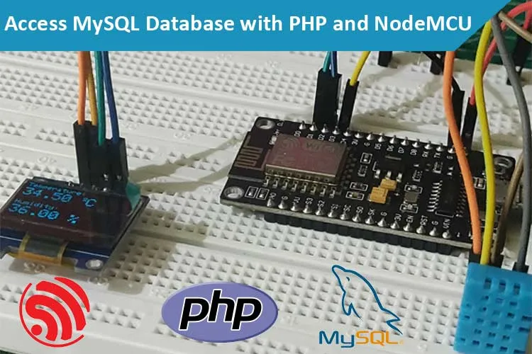
Log Data into MySQL Database using NodeMCU
In this project, we will emphasise how to interface the NodeMCU development board with a local copy of a MySQL DB using PHP. NodeMCU is a low-cost open-source IoT platform that initially included firmware which runs on the ESP8266 Wi-Fi SoC from Espressif Systems, and hardware which was based on the ESP-12 module.
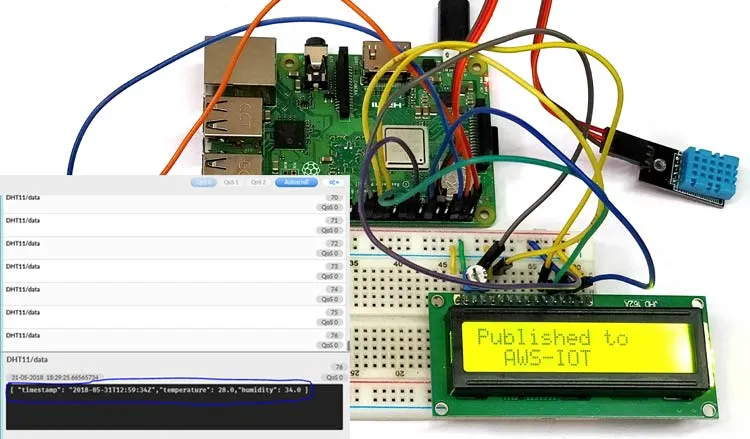
Temperature and Humidity Sensor Data to AWS - IoT
In this tutorial, we will use the DHT11 sensor to read the values of Temperature and Humidity, then connect to the AWS IOT service and update the sensor values using the AWS IOT SDK. This data can then be visualised in the Amazon IOT console to make sure we are getting the data published to the internet.
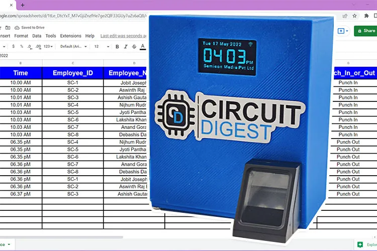
Biometric Attendance System using Google Sheets
Among the various biometric identification systems, Fingerprint identification is one of the most well-known and commonly used ones as it is fast, reliable, and tamper-proof. Because of their uniqueness & consistency over time, fingerprints have been used for identification for many years, more recently becoming automated due to advancements in computing capabilities.
Complete Project Code
/*
* ESP32-S3 CAM (N16R8): button -> RGB LED 1 s -> timestamped log in /log.txt on SD
* PLUS: the same SD card can be shown as a USB drive on your laptop.
*
* WHY TWO MODES?
*   The ESP32 and the laptop must never write to the SD card at the same time
*   (the FAT filesystem would be corrupted). So the board runs in one of two modes:
*     LOGGING MODE (default): button press -> LED on 1 s -> line appended to /log.txt
*     USB DRIVE MODE        : card appears as a drive on the laptop (LED = dim blue)
*   Long-press the BOOT button (GPIO0) for 2 s to switch modes (the board restarts).
*   The chosen mode is remembered across power cycles.
*   TIP: Eject the drive on your laptop before switching back to logging mode.
*
* ARDUINO IDE SETTINGS (Tools menu):
*   Board: ESP32S3 Dev Module | USB Mode: USB-OTG (TinyUSB) | USB CDC On Boot: Disabled
*   Flash: 16MB | PSRAM: OPI PSRAM | Arduino-ESP32 core 3.x
*   Upload and view Serial via the UART USB port; plug the native USB port into the laptop.
*
* WIRING: push button between BUTTON_PIN and GND (internal pull-up is used).
*
* TIME: logging mode syncs the time from NTP over Wi-Fi at boot (retries included).
*   There is no fake fallback time: until the time is synced, button presses
*   are NOT logged (LED shows RED instead) and the board keeps retrying.
*
* PINS below are for the Freenove ESP32-S3-WROOM CAM. Check your board's schematic.
*/
#include <WiFi.h>
#include <time.h>
#include <Preferences.h>
#include "USB.h"
#include "USBMSC.h"
#include "SD_MMC.h"
// ---------- USER SETTINGS ----------
const char *WIFI_SSID = "YOUR_WIFI_NAME";
const char *WIFI_PASS = "YOUR_WIFI_PASSWORD";
const char *TZ_INFO   = "IST-5:30";   // India Standard Time
#define SD_CLK_PIN 39
#define SD_CMD_PIN 38
#define SD_D0_PIN  40
#define LED_PIN     48   // onboard WS2812 RGB LED (Freenove CAM). Change if different.
#define BUTTON_PIN  14   // external push button to GND. Pick any free GPIO.
#define MODE_PIN     0   // BOOT button: long-press 2 s toggles mode
#define LED_ON_MS        1000
#define DEBOUNCE_MS      50
#define LONG_PRESS_MS    2000
// -----------------------------------
Preferences prefs;
USBMSC MSC;
bool usbMode = false;
bool sdOk = false;
// ---------- LED helpers ----------
void ledColor(uint8_t r, uint8_t g, uint8_t b) { neopixelWrite(LED_PIN, r, g, b); }
void ledOff() { neopixelWrite(LED_PIN, 0, 0, 0); }
// ---------- Time ----------
// A valid clock means the year is 2024 or later (i.e. NTP really set it).
bool timeValid() {
 return time(nullptr) > 1704067200;   // 2024-01-01
}
// Connects to Wi-Fi and waits (with retries) for a real NTP time.
// There is NO fake/fallback time: if this fails, it returns false and the
// sketch simply keeps retrying in the background.
bool setupTime() {
 configTzTime(TZ_INFO, "pool.ntp.org", "time.google.com", "time.cloudflare.com");
 WiFi.mode(WIFI_STA);
 WiFi.setSleep(false);
 WiFi.begin(WIFI_SSID, WIFI_PASS);
 Serial.print("Connecting to Wi-Fi");
 uint32_t t0 = millis();
 while (WiFi.status() != WL_CONNECTED && millis() - t0 < 30000) {
   delay(300);
   Serial.print(".");
 }
 Serial.println();
 if (WiFi.status() == WL_CONNECTED) {
   Serial.print("Waiting for NTP");
   for (int i = 0; i < 30 && !timeValid(); i++) {   // up to ~30 s
     delay(1000);
     Serial.print(".");
   }
   Serial.println();
 }
 WiFi.disconnect(true);
 WiFi.mode(WIFI_OFF);
 if (timeValid()) {
   Serial.println("Time synced from NTP");
   return true;
 }
 Serial.println("Time sync failed - will retry in the background");
 return false;
}
String timestamp() {
 struct tm t;
 if (!getLocalTime(&t, 100)) return "time-unavailable";
 char buf[32];
 strftime(buf, sizeof(buf), "%Y-%m-%d %H:%M:%S", &t);
 return String(buf);
}
// ---------- Logging ----------
void logLedEvent() {
 String line = timestamp() + " IST - LED turned ON";
 File f = SD_MMC.open("/log.txt", FILE_APPEND);
 if (!f) {
   Serial.println("Cannot open /log.txt");
   return;
 }
 f.println(line);
 f.close();
 Serial.println(line);
}
// ---------- USB MSC callbacks ----------
static int32_t onRead(uint32_t lba, uint32_t offset, void *buffer, uint32_t bufsize) {
 uint32_t secSize = SD_MMC.sectorSize();
 if (!secSize) return -1;
 for (uint32_t x = 0; x < bufsize / secSize; x++) {
   if (!SD_MMC.readRAW((uint8_t *)buffer + secSize * x, lba + x)) return -1;
 }
 return bufsize;
}
static int32_t onWrite(uint32_t lba, uint32_t offset, uint8_t *buffer, uint32_t bufsize) {
 uint32_t secSize = SD_MMC.sectorSize();
 if (!secSize) return -1;
 for (uint32_t x = 0; x < bufsize / secSize; x++) {
   uint8_t blk[512];
   memcpy(blk, buffer + secSize * x, secSize);
   if (!SD_MMC.writeRAW(blk, lba + x)) return -1;
 }
 return bufsize;
}
static bool onStartStop(uint8_t power_condition, bool start, bool load_eject) { return true; }
void startUsbDrive() {
 MSC.vendorID("ESP32");
 MSC.productID("SD Drive");
 MSC.productRevision("1.0");
 MSC.onRead(onRead);
 MSC.onWrite(onWrite);
 MSC.onStartStop(onStartStop);
 MSC.mediaPresent(true);
 MSC.begin(SD_MMC.numSectors(), SD_MMC.sectorSize());
 USB.begin();
 ledColor(0, 0, 8);   // dim blue = USB drive mode
 Serial.println("USB DRIVE MODE: plug the native USB port into the laptop.");
}
// ---------- Mode switching ----------
void toggleModeAndRestart() {
 prefs.putBool("usb", !usbMode);
 ledColor(40, 40, 40);   // white flash
 delay(400);
 ledOff();
 Serial.println("Switching mode, restarting...");
 delay(200);
 ESP.restart();
}
void checkModeButton() {
 static uint32_t pressedAt = 0;
 if (digitalRead(MODE_PIN) == LOW) {
   if (pressedAt == 0) pressedAt = millis();
   if (millis() - pressedAt >= LONG_PRESS_MS) {
     toggleModeAndRestart();
   }
 } else {
   pressedAt = 0;
 }
}
// ---------- Arduino ----------
void setup() {
 Serial.begin(115200);
 delay(500);
 pinMode(BUTTON_PIN, INPUT_PULLUP);
 pinMode(MODE_PIN, INPUT_PULLUP);
 ledOff();
 prefs.begin("cfg", false);
 usbMode = prefs.getBool("usb", false);
 SD_MMC.setPins(SD_CLK_PIN, SD_CMD_PIN, SD_D0_PIN);
 sdOk = SD_MMC.begin("/sdcard", true);   // 1-bit mode
 if (!sdOk) {
   Serial.println("SD card mount failed. Check card and pins.");
   ledColor(30, 0, 0);   // red = SD error
   return;
 }
 Serial.printf("SD card: %llu MB\n", SD_MMC.cardSize() / (1024ULL * 1024ULL));
 if (usbMode) {
   startUsbDrive();
 } else {
   Serial.println("LOGGING MODE");
   setupTime();
   // Create log.txt with a header if it does not exist yet
   if (!SD_MMC.exists("/log.txt")) {
     File f = SD_MMC.open("/log.txt", FILE_WRITE);
     if (f) {
       f.println("=== ESP32-S3 LED log ===");
       f.close();
     }
   }
   ledColor(0, 20, 0);  delay(150);  ledOff();   // short green blink = ready
   Serial.println("Press the push button to log. Long-press BOOT 2 s for USB drive mode.");
 }
}
void loop() {
 checkModeButton();   // works in both modes
 if (!sdOk || usbMode) {
   delay(10);
   return;
 }
 // ----- Logging mode -----
 static bool lastBtn = HIGH;
 static uint32_t lastChange = 0;
 static bool ledActive = false;
 static uint32_t ledStart = 0;
 // Time not synced yet? Keep retrying every 20 s (blocking while it tries).
 static uint32_t lastSyncTry = 0;
 if (!timeValid() && millis() - lastSyncTry > 20000 && !ledActive) {
   ledColor(20, 10, 0);         // amber = syncing time
   setupTime();
   ledOff();
   lastSyncTry = millis();
 }
 bool btn = digitalRead(BUTTON_PIN);
 if (btn != lastBtn && millis() - lastChange > DEBOUNCE_MS) {
   lastChange = millis();
   lastBtn = btn;
   if (btn == LOW && !ledActive) {      // button pressed
     ledActive = true;
     ledStart = millis();
     if (timeValid()) {
       ledColor(0, 60, 0);              // green ON
       logLedEvent();
     } else {
       ledColor(60, 0, 0);              // red = time not synced, nothing logged
       Serial.println("Time not synced yet - press not logged");
     }
   }
 }
 if (ledActive && millis() - ledStart >= LED_ON_MS) {
   ledOff();
   ledActive = false;
 }
}

Add a comment
No account needed. Your comment appears once a moderator has reviewed it.