

Indoor and outdoor air pollution significantly impacts human health, causing respiratory issues and reducing life expectancy. Personal air quality monitoring has become essential for protecting ourselves from harmful airborne contaminants like volatile organic compounds (VOCs), particulate matter, and toxic gases. This DIY wearable air quality monitor pendant continuously tracks Total Volatile Organic Compounds (TVOC) levels using the professional SGP40 sensor. The device features intuitive LED color coding and audio alerts, making air quality status immediately recognizable for users of all ages. When dangerous pollution levels are detected, the wearable air quality monitor provides instant warnings to help you move to safer environments.
This comprehensive tutorial covers everything needed to build your own wearable air quality monitoring system, including circuit design, PCB fabrication, 3D printing, and Arduino programming for the STM32 microcontroller. We have also built a lot of other electronics projects here at CircuitDigest, and many air quality monitoring projects if you are looking for something simple and beginner-friendly check out this arduino air quality monitoring system.
Air Quality Pendant Overview and Features
Have you ever wondered about the air quality in your home or office? This wearable air quality pendant answers that question by monitoring TVOC levels throughout your day. Using the reliable SGP40 sensor, it gives you instant feedback through color-changing LEDs and gentle musical tones - no complicated readings to interpret. The best part? The smooth LED transitions and pleasant alert sounds make it feel more like a piece of smart jewelry than a technical device.
What makes this air quality monitor special is how smartly it works behind the scenes. The STM32 microcontroller multitasks seamlessly like reading sensors, updating displays, and playing alerts without any lag. It's like having a tiny environmental scientist on your chest, constantly checking the air and letting you know when things change. Whether you're at home cooking dinner, working in an office, or visiting a new building, you'll always know what you're breathing.
Components Required for Air Quality Monitor
Building a wearable air quality monitor requires carefully selected low-power components to ensure all-day battery operation. Each component in this TVOC monitoring system was chosen for optimal energy efficiency without compromising air quality detection accuracy. This project was made possible, thanks to our sponsor DigiKey, from whom we have purchased all the components used in this project. You can also check out the BOM, Circuit, Gerber, and Firmware Files for this projects.
STM32U083KCUx: An ultra-low-power microcontroller based on the high-performance Arm® Cortex®-M0+ 32-bit RISC core, operating at a frequency of up to 56 MHz. You can also check out our other STM32 Projects.
SGP40: A digital indoor air quality sensor for VOC measurements, offering long-term stability, a long lifetime, and very low power consumption.
ADPL44002: A CMOS low dropout (LDO) linear regulator that operates from 2.7V to 40V and provides up to 200mA of output current.
MCP73831/2: A highly advanced linear charge management controller for use in space-limited, cost-sensitive applications.
EAST1616RGBA1: A common cathode RGB LED used for indication purposes.
SS8550: A general-purpose PNP transistor for switching the buzzer.
PKMCS0909E4000-R1: A piezoelectric SMD sounder.
Other passive components
Connectors
Custom PCB
3D printed parts
Other tools and consumables
Wearable Air Quality Pendant Circuit Diagram
The complete circuit diagram for the Wearable Air Quality Pendant is shown below. It can also be downloaded in PDF format from the GitHub repo linked at the end.

The schematic is fully customizable. You can tweak any part of the design to suit your specific needs. For instance, we made a few adjustments, such as changing the resistor value in the buzzer driver circuit and modifying the charging current programming resistor in the battery section. Depending on your requirements—such as buzzer loudness or battery capacity—you’re free to modify these values as needed.
Power Management Circuit
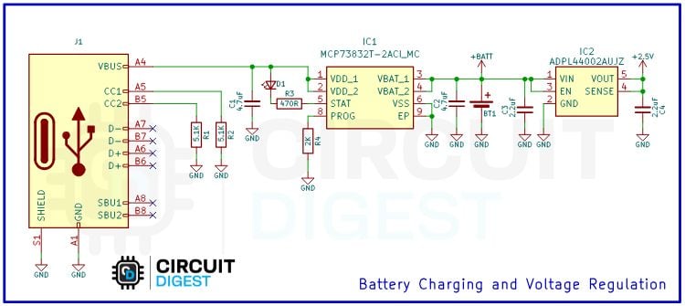
First, let's discuss about power management Section. The power management section centers around the J1 USB connector, which provides 5V power input for both charging and operation. The MCP73832T (IC1) serves as a single-cell Li-Po battery charge controller, implementing a constant current/constant voltage charging algorithm with the PROG pin setting the charging current through an external resistor, while a status LED provides visual indication of the charging state. The ADPL6400ZAU12 (IC2) functions as a low-dropout voltage regulator that converts the variable battery voltage of approximately 3.7V to a stable +2.5V supply for the entire system, which is essential for consistent sensor operation and microcontroller stability.
SGP40 Air Quality Sensor Interface
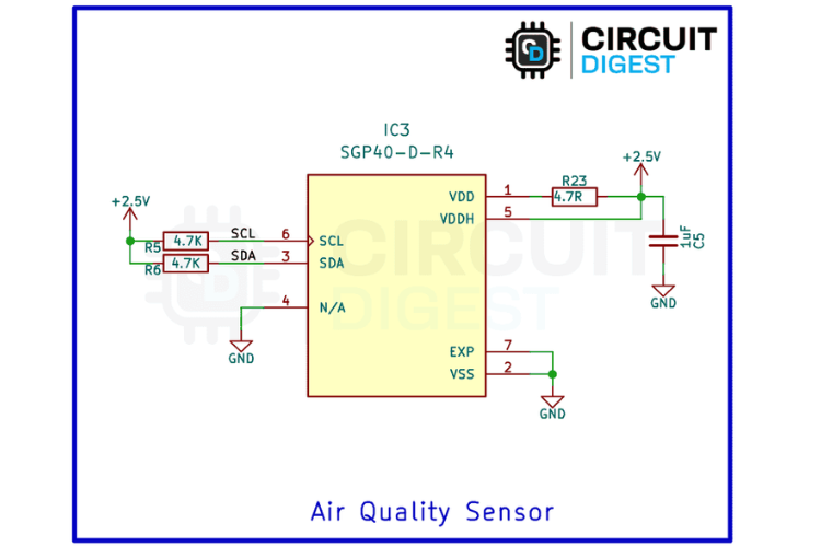
Next comes the The SGP40,Air Quality sensor responsible for measuring Total Volatile Organic Compounds in the surrounding air. This professional-grade sensor communicates with the microcontroller through I2C protocol using dedicated SCL (PA7) and SDA (PA6) lines. The sensor operates on the regulated +2.5V supply to ensure accurate and consistent measurements. Pull-up resistors R5 and R6, both valued at 4.7kΩ, are connected to the I2C lines to ensure proper signal levels and reliable communication between the sensor and microcontroller.
This digital I2C output eliminates the need for analog-to-digital conversion, reducing potential errors and simplifying the interface design. The sensor's low power consumption characteristics make it well-suited for battery-powered applications while maintaining the precision required for professional air quality monitoring.
STM32 Microcontroller Programming Interface
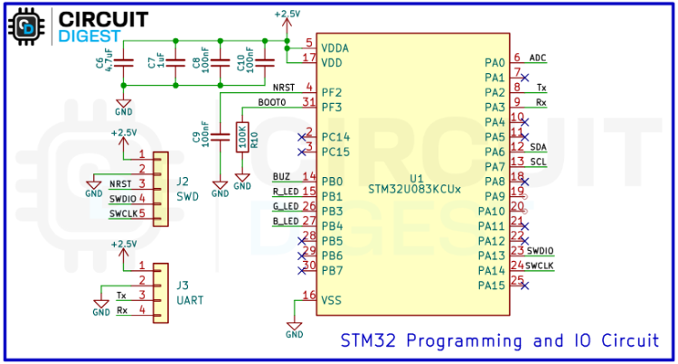
Above you can see The STM32L052UCx microcontroller, that serves as the main processing unit, handling sensor communication, data processing, and output control throughout the system. This particular microcontroller from the STM32L series is specifically chosen for its low power design characteristics, making it ideal for battery-powered applications while providing sufficient processing capability for air quality monitoring tasks.
The programming interface includes both UART (J3) for serial programming and debugging, as well as SWD interface pins (SWDIO and SWCLK) (J2) for in-circuit programming and development.
LED and Buzzer Feedback System
At last come the Visual and Audio Feed back system that is responsible for the Alerting the User based on the Air Quality.

The audio component centers around the SS8550 PNP transistor (Q1) which serves as a driver for the passive buzzer (BZ1). This configuration allows the microcontroller to generate RTTTL tones that correspond to different air quality levels, providing musical audio feedback that matches the urgency of each situation.
The visual feedback system employs four identical RGB LED driver circuits (D2-D5), each containing a complete LED_RGBK package with Red, Green, Blue, and Cathode connections. This arrangement enables precise color control and mixing to create the desired visual indicators. The system implements a sophisticated color coding scheme where green indicates good air quality (TVOC 0-200), yellow represents warning levels (TVOC 201-300), and red signals alarm conditions (TVOC 301-500).
With this, the Schematic part gets covered. Next comes the PCB Part.
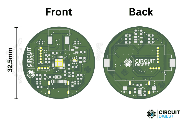
PCB Design for Wearable Air Quality Pendant
For this project, we decided to create a custom PCB. This ensures that the final product is as compact as possible and easy to assemble and use.
We have previously built a lot of PCB projects, and if you are new to PCBs you can check out the basics of PCB tutorial on our website. The PCB here was designed using KiCad, and all the design files are available for download from the GitHub repository linked below this article. The PCB has a diameter of approximately 32.50 mm.
Once the PCB design was complete and fully verified, we sent the respective Gerber files to a PCB fabrication service for manufacturing.
PCB Assembly and Soldering Guide
The first step in assembling the PCB was to sort all the required components as listed in the BOM (Bill of Materials). After sorting, we placed the components on the PCB and soldered them one by one.
To simplify this process, you can use an SMD stencil to apply solder paste and then place the components before reflowing the PCB using either an SMD rework station or a reflow oven. However, you are not limited to these methods—manual soldering works just as well for small batches.
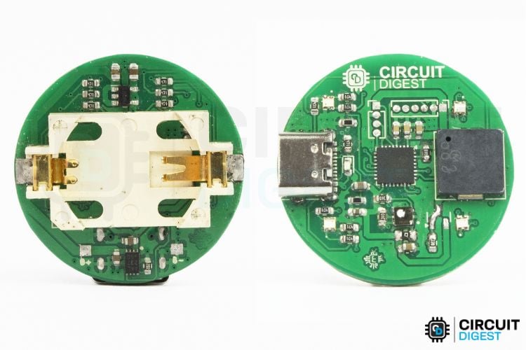
Above is the image of a fully assembled Wearable Air Quality Pendant PCB.
3D-Printed Enclosure Design
We also designed a 3D-printed enclosure to house the PCB, complete with a hook to allow the device to be worn as a pendant. The STL files for this enclosure are available in the GitHub link below.
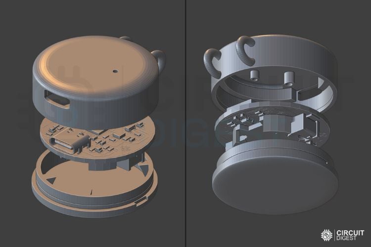
The enclosure requires minimal supports. If needed, you can use a brim to improve bed adhesion and reduce warping. You can learn more about 3D printing and how to get started by following the provided link.
Complete Assembly Instructions
With your custom PCB populated and 3D-printed enclosure ready, assembling this wearable air quality monitoring device is straightforward. The compact design ensures your personal TVOC detector fits comfortably as an everyday pendant while providing continuous air quality protection.
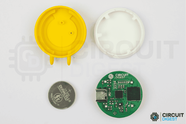
Assembly is simple, as the number of components is minimal. After inserting the battery into the battery holder, place the PCB into the top enclosure, aligning it with the USB Type-C cutout. Then, use the bottom cover to snap the enclosure closed, ensuring a secure fit.
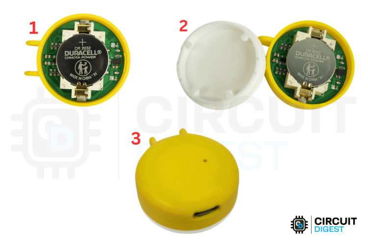
As shown above, these steps complete the physical assembly. Next, let's move on to the programming phase.
Arduino Code for Air Quality Monitoring
Programming this STM32-based air quality monitor differs from standard Arduino boards, requiring an ST-Link programmer for firmware upload. The Arduino IDE code for this wearable TVOC sensor combines real-time air quality monitoring with intelligent alert systems, making it perfect for continuous environmental sensing applications. For more Arduino programming examples, explore our Arduino Project Collection.
Library Setup and Pin Configuration
#include <DFRobot_SGP40.h>
#include <HardwareSerial.h>
#include <Arduino.h>
#include <PlayRtttl.hpp>
#include <ptScheduler.h>
The code begins by including essential libraries for the air quality monitoring system. The DFRobot_SGP40 library provides a communication interface with the SGP40 TVOC sensor, while HardwareSerial enables UART communication for data logging. The PlayRtttl library handles musical tone generation from text-based RTTTL strings, and ptScheduler implements non-blocking task scheduling to manage multiple concurrent operations without freezing the system. All these libraries are available in the the Arduino Built in library manager.
#define RED_PIN PB3
#define GREEN_PIN PB4
#define BUZZER_PIN PB0
HardwareSerial MyLPUART1(PA3, PA2);
Pin definitions establish the hardware connections with RED_PIN and GREEN_PIN controlling the visual indicators on PB3 and PB4 respectively, while BUZZER_PIN on PB0 drives the audio alerts. A custom LPUART serial interface is configured using PA3 for receive and PA2 for transmit, enabling communication with external devices or computers for data monitoring and debugging purposes.
int tvoc = 0;
int toneRequest = -1;
int fadeStep = 0;
unsigned long prevLedTime = 0;
unsigned long prevToneTime = 0;
The global variables manage the system state and timing operations. The tvoc variable stores the current Total Volatile Organic Compounds reading from the sensor, while toneRequest acts as a flag indicating which audio-visual alert should be activated. The fadeStep variable tracks the LED fading animation progress, and timing variables prevLedTime and prevToneTime implement non-blocking delays for periodic operations.
const char softTone[] = "Soft:d=8,o=5,b=100:g";
const char warnTone[] = "Warn:d=4,o=5,b=120:c,e,g";
const char alarmTone[] = "Alarm:d=16,o=5,b=180:c6,c6,c6";
const char startTone[] = "Start:d=8,o=6,b=120:c,e,g";
const char errorTone[] = "Error:d=4,o=5,b=160:c,c,r,c";
enum ToneType {
 TONE_SOFT = 5000,
 TONE_WARN = 2000,
 TONE_ALARM = 500,
 TONE_START = 1000,
 TONE_ERROR = 200
};
Five RTTTL tone strings define the musical sequences for different system states. The softTone provides a gentle single G note for good air quality, warnTone plays an ascending C-E-G progression for warning conditions, and alarmTone generates rapid triple beeps for urgent situations. Additional tones include startTone for system initialization and errorTone for fault conditions. The ToneType enumeration cleverly associates each tone with its playback interval in milliseconds, creating a unified timing system where TONE_SOFT repeats every 5 seconds, TONE_WARN every 2 seconds, TONE_ALARM every 500 milliseconds, and TONE_ERROR every 200 milliseconds for maximum urgency.
ptScheduler readSensorTask(PT_TIME_1S);   // Sensor reading every 1 second
ptScheduler lightTask(PT_TIME_100MS);     // LED update task
ptScheduler soundTask(PT_TIME_100MS);     // Buzzer task
Three ptScheduler objects manage the timing of different system tasks without blocking program execution. The readSensorTask triggers sensor readings every second, lightTask updates LED effects every 100 milliseconds for smooth fading, and soundTask handles audio playback timing at 100-millisecond intervals.
The setup function initializes all system components and establishes communication interfaces. Serial communication begins at 115200 baud rate through the custom LPUART interface, providing high-speed data transfer for real-time monitoring. All output pins are configured using pinMode to enable proper control of the LEDs and buzzer, ensuring the hardware responds correctly to software commands.
void setup() {
 MyLPUART1.begin(115200);
 pinMode(RED_PIN, OUTPUT);
 pinMode(GREEN_PIN, OUTPUT);
 pinMode(BUZZER_PIN, OUTPUT);
 MyLPUART1.println("sgp40 is starting, the reading can be taken after 10 seconds...");
 updateLedFade(TONE_START);
 playTone(TONE_START);
 if (!mySgp40.begin(10000)) {
   MyLPUART1.println("Failed to init chip. Please check connection.");
   showErrorState();
   while (true);
 }
 MyLPUART1.println("sgp40 initialized successfully!");
}
A startup message informs users that the SGP40 sensor requires a 10-second warm-up period before providing accurate readings, which is typical for gas sensors that need time to stabilize their internal chemistry. The system immediately provides visual and audio feedback through updateLedFade and playTone functions, giving users confidence that the device is operational and initializing properly.
The SGP40 sensor initialization uses the begin function with a 10-second timeout parameter, allowing sufficient time for the sensor to establish communication and complete its internal calibration. If initialization fails, the system immediately enters an error state with continuous error tones and LED flashing, then halts execution to prevent unreliable operation. Success results in a confirmation message, and the system proceeds to normal monitoring operation.
TVOC Sensor Reading and Alert System
The main loop implements a sophisticated non-blocking architecture using the ptScheduler system to manage multiple concurrent tasks without interfering with each other. The readSensorTask scheduler triggers the readAndEvaluateAir function every second, ensuring consistent air quality monitoring while allowing other operations to continue smoothly between readings.
void loop() {
 if (readSensorTask.call()) {
   readAndEvaluateAir();
 }
 if (lightTask.call() && toneRequest != -1) {
   updateLedFade((ToneType)toneRequest);
 }
 if (soundTask.call() && toneRequest != -1 && toneRequest != TONE_SOFT) {
   playTone((ToneType)toneRequest);
 }
}
The readAndEvaluateAir function retrieves the current TVOC index from the SGP40 sensor and immediately logs this value via serial communication for external monitoring or data analysis. The function then evaluates the reading against predefined thresholds to classify air quality into four categories. TVOC values from 0 to 200 indicate good air quality and trigger the soft tone with green LED indication. Values between 201 and 300 represent warning conditions with yellow LED display created by combining red and green LEDs. Readings from 301 to 500 activate alarm mode with red LEDs and urgent audio alerts. Any reading above 500 or sensor communication failure triggers the error state with rapid flashing and beeping.
Visual feedback is managed through the updateLedFade function, which implements a sophisticated PWM-based fading algorithm that creates smooth color transitions rather than harsh on-off switching. The function calculates target brightness levels for red and green LEDs based on the current air quality state, then gradually fades the LEDs in and out using nested loops with precise timing control. This creates an aesthetically pleasing and attention-getting display that clearly communicates air quality status without being jarring or distracting.
Audio alerts are handled by the playTone function, which uses timing control to ensure tones play at appropriate intervals without blocking other operations. The function employs the PlayRtttl library to convert text-based musical notation into PWM signals that drive the buzzer, creating distinct musical patterns that users can easily associate with different air quality levels. The system intelligently skips soft tones during good air quality conditions to avoid unnecessary noise while maintaining alertness for warning and alarm situations.
The error handling system provides robust fault detection and user notification through the showErrorState function, which immediately activates visual and audio error indicators when sensor communication fails or readings exceed normal ranges. This ensures users are promptly notified of system malfunctions or extremely dangerous air quality conditions that require immediate attention.
Download Complete Project Files
The GitHub repository includes the complete Arduino code for the Wearable Air Quality Pendant


Related Air Quality Monitoring Projects
Previously we have build many interesting projects on air quality Monitoring System. If you want to know more about those topics, links are given below.

Arduino Air Quality Monitoring System
Build an Arduino-based air quality monitoring system using the MQ135 sensor to detect harmful gases like CO₂, NH₃, and benzene. Learn circuit design, interfacing, and code to monitor pollution levels and ensure a healthier environment.

TVOC and CO2 Measurement using Arduino and CCS811 Air Quality Sensor
Learn how to measure TVOC and CO₂ levels using Arduino and the CCS811 air quality sensor. This project guides you through interfacing, circuit setup, and coding to monitor indoor air quality effectively for health and safety.

IoT Based Air Quality Index Monitoring System – Monitor PM2.5, PM10, and CO using ESP32
Build an IoT-based Air Quality Index Monitoring System using ESP32 to measure PM2.5, PM10, and CO levels. This project helps you track pollution in real time with sensor integration and Wi-Fi connectivity for smart environmental monitoring.

Interfacing Sharp GP2Y1014AU0F Sensor with Arduino to build Air Quality Analyser
Learn how to interface the Sharp GP2Y1014AU0F dust sensor with Arduino to build a simple air quality analyzer. This project detects dust particles and provides real-time air pollution data, making it ideal for environmental monitoring applications.

IoT based Air Pollution Monitoring System using Arduino
Build an IoT-based air pollution monitoring system using Arduino. This project uses sensors to detect harmful gases and sends real-time air quality data to the cloud for remote monitoring and analysis. Ideal for smart city and environmental applications.
