 Vedhathiri
Author

A robotic arm is one of the most popular projects that almost every electronics enthusiast tries to build at least once in their life. Robotic arms are fascinating projects because they can be built for many practical applications, such as pick-and-place operations, component assembly, repetitive tasks, and even creating intelligent systems like the robotic arm “Dummy” seen in the Iron Man movie. These robotic arms are mainly used in environments where hazardous chemicals must be handled safely or where tasks are complex but repetitive, and in the electronics industry, they are widely used for PCB assembly because they can work faster and with higher accuracy than humans. Okay, let’s make an Arduino robotic arm that is easier to operate and simpler to build. If you need more ideas in the robotics field, just give our robotic projects a try. This comprehensive robotic arm project using Arduino demonstrates how to create a fully functional 6 DOF robotic arm capable of performing pick and place robotic arm operations with precision and reliability.
Our robotic arm Arduino project includes a complete robotic arm circuit diagram, detailed Arduino robotic arm code, and step-by-step assembly instructions for building a robotic arm with servo-motor actuation. Whether you're interested in industrial automation, educational robotics, or simply exploring mechatronics, this Arduino robotic arm 3D print tutorial provides hands-on experience with robotic arm components, servo motor control, and embedded programming.
6-DOF Arduino Robotic Arm with Web Dashboard - Quick Overview
Build Time: 10-20 hours | Difficulty: Intermediate
What You'll Learn: Servo motor control, PWM signal generation, Serial communication, Web Serial API (JavaScript), 3D printing & mechanical assembly, Smooth motion interpolation
Applications: Pick-and-place automation, Educational robotics demonstrator, Laboratory sample handling, Repetitive task prototyping, Hobby mechatronics learning
Table of Contents
- What is an Arduino Robotic Arm?
- └ Key Components of a 6 DOF Robotic Arm
- Robotic Arm Fundamentals
- Components Required
- Circuit Diagram
- Hardware Setup and Assembly
- Arduino UNO Pinout Configuration
- 3D Printing Process
- Code Explanation
- Web-Based Control Dashboard
- Operating the Arduino Robotic Arm
- Real-World Applications
- Troubleshooting
- GitHub Repository
What is an Arduino Robotic Arm?
An Arduino robotic arm is a mechanical device designed to replicate the movements and functions of the human arm, enabling it to perform tasks with high accuracy, repeatability, and full programmable control. It is constructed from multiple rigid segments connected by joints, allowing the robotic arm with servo motor to move in various directions through different degrees of freedom (DOF). The greater the number of degrees of freedom (4 DOF or 6 DOF robotic arm), the more flexible and capable the robotic arm becomes. Robotic arms are widely used across many industries, from factories where they assemble cars, weld metal, arrange components, and paint surfaces perfectly, to the medical field where they assist surgeons in procedures that demand extreme accuracy and stability. They are also commonly found in laboratories, space missions, and educational environments, etc. If you’re interested in more versions of robotic arms, you can look at our Bluetooth-Controlled Pick and Place Robotic Arm Car and Record and Play 3D Printed Robotic Arm using Arduino projects.
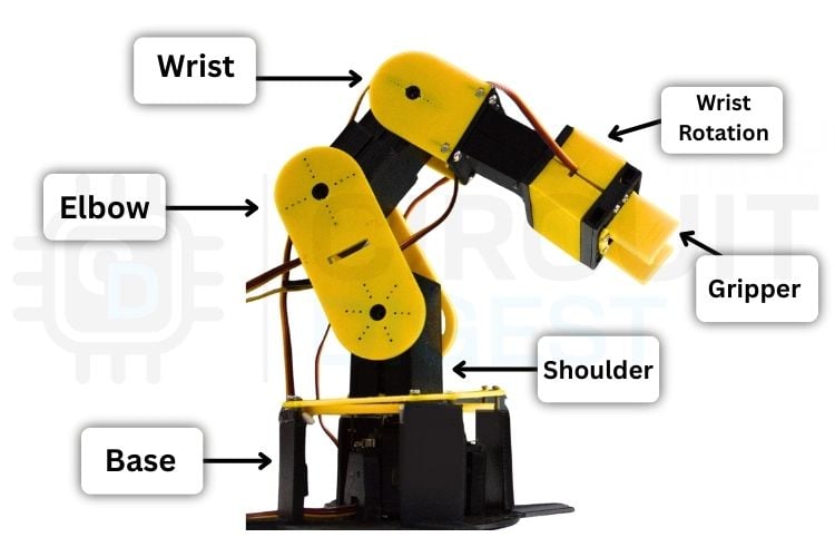
Key Components of a 6 DOF Robotic Arm
| Component | Function |
| Base Joint | 360-degree rotation around vertical axis |
| Shoulder Joint | Vertical arm movement (up/down) |
| Elbow Joint | Arm extension and retraction |
| Wrist Pitch | End effector angle adjustment |
| Wrist Rotation | Gripper orientation control |
| Gripper | Object grasping mechanism |
Robotic Arm Fundamentals - Concepts Every Builder Should Know
Before starting the Arduino robotic arm project, it’s important to understand a few fundamental concepts that apply to almost every robotic arm design. These terms will help you plan better, avoid common mistakes, and build a smoother robotic arm.
Robotic Arm Joints
Joints are the moving connections in a robotic arm that allow it to bend, rotate, or change direction, similar to human joints like elbows and wrists. Each joint contributes to the arm’s overall movement. For example, in a 6-axis robotic arm, six independent joints work together to achieve complex positioning and smooth motion in 3D space.
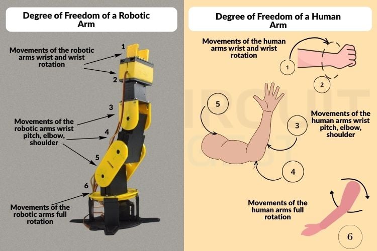
6 Degrees of Freedom (DOF)Robotic arm
Degrees of freedom describe how many independent movements a robotic arm can perform. A 1-DOF arm can move in only one direction, while a 3-DOF arm can move up and down, side to side, and rotate. As the number of DOF increases, the robotic arm Arduino becomes more flexible, capable, and closer to human-like movement.
Servo Motor Fundamentals for Robotic Arms
Most beginner robotic arm with servo motor for precise control. Servos rotate to specific angles based on control signals and are ideal for accurate positioning in Arduino robotic arm applications. Typically, hobby servos rotate within a limited range, such as 0 -180 degrees, provide excellent position control, and have torque ratings that determine how much weight the arm can lift. Understanding servo behavior is critical because weak or overloaded servos can limit your entire project.
3D Design and Modelling for Robotic Arms
Arduino robotic arm 3D printing involves creating the robotic arm’s parts using CAD software like Fusion 360 or SolidWorks. These designs are then 3D-printed or machined. Good 3D modelling ensures smooth motion, correct fitting, and sufficient strength.
Rotation Limits and Range of Motion
Every joint or servo has physical rotation limits. Most hobby servos rotate up to 180 degrees, while some specialized designs allow full 360-degree rotation. These limits define the arm’s working area and directly influence mechanical design decisions in a DIY robotic arm project using Arduino.
Power Supply Requirements for Servo Motors
Robotic arms with multiple servos require a stable and adequate power supply. USB power is usually not enough, and servos often need a separate power source. Both voltage and current ratings are important; insufficient current can cause shaking, overheating, or servo damage.
Control System Selection for Arduino Robotic Arms
The controller acts as the brain of the robotic arm and determines its capabilities. Arduino boards are great for simple pick-and-place tasks, Raspberry Pi supports advanced processing and vision systems, and ESP32 enables wireless control and IoT integration
Components Required for Arduino Robotic Arm
This comprehensive list details all robotic arm components required for constructing a fully functional 6-DOF robotic arm. Each component plays a specific role in the mechanical structure, electronic control, or power delivery system of this Arduino robotic arm project
| S.No | Component | Quantity | Purpose |
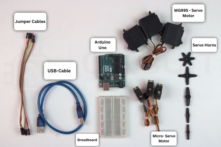
| 1. | Arduino UNO | 1 | Main microcontroller used to control the robotic arm |
| 2. | Micro-Servo motor | 3 | Used for precise movement of smaller joints |
| 3. | MG995 Servo motor | 3 | Used for high-torque movement of major joints |
| 4. | Breadboard | 1 | Used for temporary circuit connections |
| 5. | Jumper wires | As required | Used to connect all electronic components |
| 6. | 3D printed parts | As required | Used to build the mechanical structure of the robotic arm |
| 7. | Screws, nuts, bolts | 1 set | Used to assemble and fix the joints together |
| 8. | Screwdriver set | - | Used for mechanical assembly |
| 9. | Arduino IDE | - | Used to write and upload code to the Arduino |
| 10. | External power (5V,2A) | 1 | Used to power the servo motors |
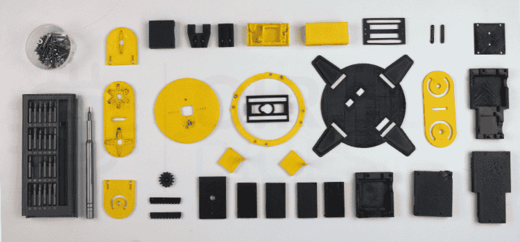
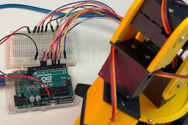
The picture above shows the various 3D printed robotic arm parts, screw set for assembling, and the picture below shows the controller for the programming, and motors for the movement, etc.
Arduino Robotic Arm Circuit Diagram: Wiring Guide and Servo Motors
The Arduino Robotic Arm Circuit Diagram shown below provides a clear understanding of how all the components are connected in the robotic arm setup. In this setup, the Arduino Uno microcontroller acts as the brain of the robotic arm, where the control program is written and uploaded. All six servo motors are connected to the PWM pins of the Arduino Uno to precisely control the movement of each joint.

A breadboard is used as a common interconnection platform for wiring the components neatly. An external power supply is connected to the breadboard’s power and ground rails, allowing the required power and ground to be distributed commonly to all servo motors and other components.
Hardware Setup and Assembly of the Arduino Robotic Arm
The hardware setup plays a crucial role in ensuring the robotic arm operates smoothly and reliably in real time. Each component is connected carefully to avoid loose wiring or unstable power delivery, which could interrupt operation. The motors are firmly mounted to the arm structure so they remain stable during movement, preventing unwanted vibrations or jitter. Each motor is connected to the PWM pins of the Arduino UNO for control, and then power and ground are given externally to the motors to operate properly.
Arduino UNO Pinout Configuration for Robotic Arm Servo Control
The table shows the pin configuration of the Arduino UNO–based robotic arm. The red (VCC) wires of all servos are connected to the breadboard positive rail, and the brown/black (GND) wires are connected to the breadboard ground rail. The Arduino GND is connected to the same ground rail to maintain a common reference.
| S.NO | Components | Quantity | Arduino UNO Pin | Power / Ground Connection |
| 1 | MG995 Servo | 1 | D3 | Common external power supply |
| 2 | MG995 Servo | 1 | D5 | Common external power supply |
| 3 | MG995 Servo | 1 | D6 | Common external power supply |
| 4 | MG90S | 1 | D9 | Common external power supply |
| 5 | MG90S | 1 | D10 | Common external power supply |
| 6 | MG90S | 1 | D11 | Common external power supply |
| 7 | External Power pack | - | - | Connected to breadboard VCC and GND rails |
| 8 | Arduino UNO | - | - | Common ground shared with external supply |
| 9 | Breadboard | - | - | - |
| 10 | Jumper Wires | Required amount | - | - |
3D Printing Process for Robotic Arm Structural Components
The robotic arm parts were fabricated using 3D printing, as shown in the image below. All major mechanical components, such as the base, arm links, joints, and gripper, were printed separately and later assembled to form the complete robotic arm structure.
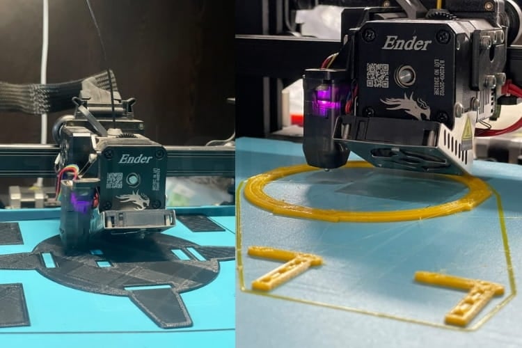
After printing, the parts were checked for proper fitting and alignment, and the servo motors were mounted into their respective slots. The printed components were then assembled step by step using screws to ensure smooth movement of each joint. This 3D printing makes the robotic arm lightweight, easy to assemble, and suitable for rapid prototyping. If you're interested in open-source robotic arm projects, check out this list of the Top 10 Open-Source Robotic Arms for Beginners.
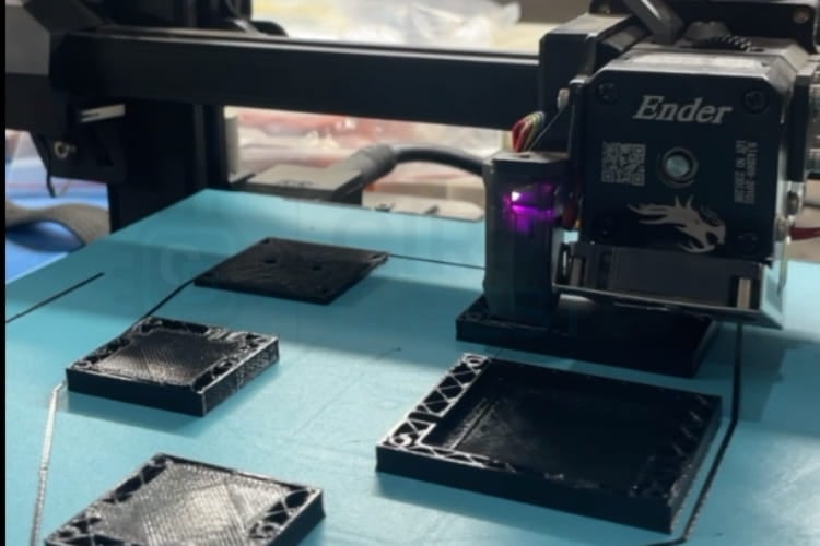
To make the robotic arm look good, we used two filaments to print the robotic arm. One is a yellow filament, and another one is a black filament. Yellow filament is used to print the moving parts, and the black filament is used to print the enclosure base parts.
The 3D models used for printing the robotic arm were sourced from an open-source project available on Instructables. The same reference was also used for understanding the mechanical assembly of the robotic arm. You can refer to the link below for the open-source 3D files and assembly steps.
Source Link
https://www.instructables.com/3D-Printed-Arduino-Based-Robotic-Arm/
Arduino Robotic Arm Code Explanation
This Arduino robotic arm code controls a 6-DOF robotic arm using servo motors through serial commands. Each servo (base, shoulder, elbow, wrist rotation, wrist pitch, and gripper) can be moved smoothly to a target angle with defined safety limits. The arm initialises to a safe starting position and supports real-time position feedback via serial communication. To make this more improved, we created the dashboard that is used to control the robotic arm by the sliders, and the control datas are send via the serial port. The dashboard feature will be explained later.
Servo Object Declaration and Initialization
#include <Servo.h>
Servo base, shoulder, elbow, wristRot, wristPitch, gripper;
int BASE_INIT = 90;
int SHOULDER_INIT = 90;
int ELBOW_INIT = 90;
int WRIST_ROT_INIT = 90;
int WRIST_PITCH_INIT = 90;
int GRIPPER_INIT = 90;
This section creates six Servo objects, one for each joint of the robotic arm.
Initial angles are set to 90°, placing the arm in a neutral and safe alignment. Starting all servos from the center position reduces mechanical stress. This also ensures predictable motion when commands are sent later.
Setup Function: PWM Pin Assignment and Serial Communication
const int SERVO_STEP_DELAY = 15;
void setup() {
Serial.begin(9600);
 base.attach(3);
 shoulder.attach(5);
 elbow.attach(6);
 wristRot.attach(10);
 wristPitch.attach(11);
 gripper.attach(9);
}
SERVO_STEP_DELAY controls how smooth the servo movement appears. All servos are attached to their respective Arduino PWM pins, capable digital pins matching the robotic arm circuit diagram specifications. Serial communication is initialised for command-based control. This setup prepares the hardware and communication interface.
Initial Position Configuration
delay(500);
base.write(BASE_INIT);
shoulder.write(SHOULDER_INIT);
elbow.write(ELBOW_INIT);
wristRot.write(WRIST_ROT_INIT);
wristPitch.write(WRIST_PITCH_INIT);
gripper.write(GRIPPER_INIT);
After powering up, the servos are given time to stabilize. Each servo is moved to its predefined initial angle. This prevents sudden jerks or unsafe movements at startup. A confirmation message is sent to indicate readiness.
Serial Command Processing and Safety Constraints
String command = Serial.readStringUntil('\n');
char joint = command.charAt(0);
int angle = command.substring(1).toInt();
angle = constrain(angle, 0, 180);
The program reads serial commands like B90 or S45.
The first character selects the joint, and the number sets the angle.
constrain() ensures the servo stays within safe mechanical limits.
Invalid joints are detected and rejected to prevent errors.
Smooth Motion Control Function
void moveServoSmooth(Servo &servo, int targetAngle) {
 int currentAngle = servo.read();
 for (int pos = currentAngle; pos <= targetAngle; pos++) {
   servo.write(pos);
   delay(SERVO_STEP_DELAY);
 }
}
This function moves the servo gradually instead of instantly. The servo steps through angles one degree at a time. Delays between steps create smooth, realistic motion. This reduces vibration, current spikes, and mechanical wear.
Web-Based Control Dashboard for Arduino Robotic Arm
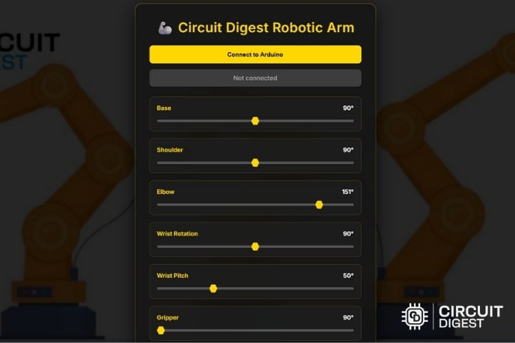
The robotic arm is controlled using a web-based dashboard developed with HTML, CSS, and JavaScript. This dashboard is designed as a plug-and-play interface, meaning no additional installation or configuration is needed. You need to save the file with the .html extension and open it in a web browser.
Once it is opened, the dashboard connects to the Arduino via Web Serial communication and provides real-time control of all servo motors by sliders. Each slider is responsible for each joint in the robotic arm. The dashboard also includes features such as reset positions, record motion, playback recorded movements, and save/load motion sequences, enabling smooth and repeatable arm operations. For a foundational understanding of robotic arm design and control without using 3D-printed parts, explore our DIY Arduino Robotic Arm Tutorial.
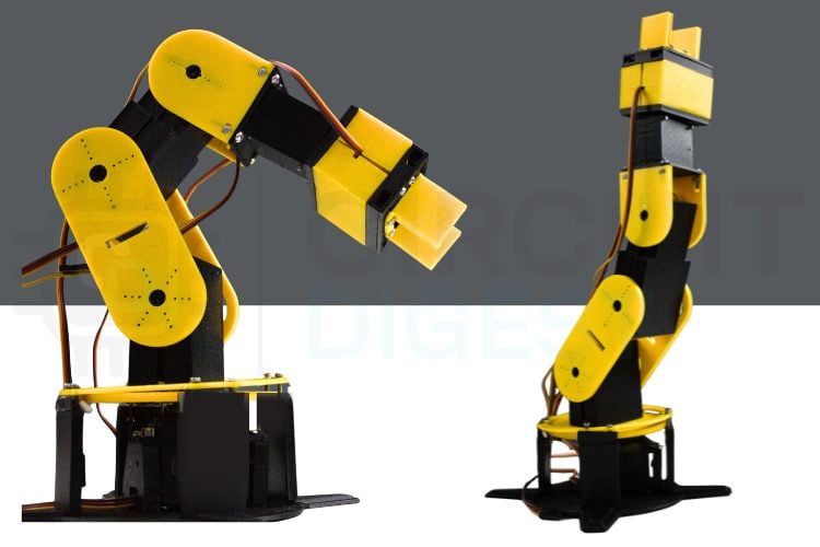
Operating the Arduino Robotic Arm
After assembling all the 3D-printed parts, the robotic arm will appear as shown in the image below. Place the assembled robotic arm on a flat and stable table to ensure proper alignment. Next, connect the motor wires according to the circuit diagram provided. Once the wiring is complete, connect the Arduino UNO microcontroller to your PC or laptop using a USB cable. Before uploading the source code, make sure that all servo motors are set to their initial position of 90 degrees. This step is important for the smooth movement of the robotic arm. If any motor is not aligned at 90 degrees, manually adjust it before proceeding. After confirming the initial alignment, upload the source code to the Arduino UNO and begin operating the robotic arm.
After uploading the Arduino robotic arm code to the microcontroller, the robotic arm with the servo motors will move to the initial positions defined in the source code. Next, open the saved dashboard HTML file in Google Chrome, where the control interface with sliders will be displayed. Each slider corresponds to a specific joint of the robotic arm, including the base, shoulder, elbow, wrist pitch, wrist rotation, and gripper. By sliding the controls forward and backwards, you can manually control the movement of each joint in real time.
The dashboard also allows you to record and replay movements. To record a motion sequence, click the Record button on the dashboard and then move the sliders as required. Once all desired movements are completed, click the Stop button to end the recording. After stopping, click the Save option to store the recorded sequence as a JSON file, which contains all the joint movements and timing information. To replay the motion, click the Load option on the dashboard, select the saved JSON file from the file manager, and then click Play. The robotic arm will automatically perform the recorded movements exactly as saved. Also, explore our detailed tutorial on designing and controlling a 3D-printed robotic arm with a PIC microcontroller.
Real-World Applications of Arduino Robotic Arms
Hazardous Environment Operations
Robotic arms can perform tasks in dangerous environments, such as handling chemicals, explosives, or radioactive materials, keeping humans safe. Remote-controlled industrial robotic arms perform dangerous tasks in environments where difficult for human workers.Education and Research
Affordable robotic arms using Arduino and 3D printed robot arms serve as excellent educational tools, providing hands-on experience with robotics principles, automation fundamentals, programming concepts, and engineering problem-solving.Laboratory Automation
Robotic arms can handle the test tubes, samples, and looped lab tasks, which also helps in reducing human error. Pick and place robotic arms automate repetitive laboratory tasks: pipetting samples, handling test tubes, organising specimens, and executing standard protocols.Medical and Surgical Assistance
These will assist in precise surgical procedures and handling delicate medical tasks that require stability and accuracy. Specialised 6-axis robotic arms assist surgeons in minimally invasive procedures requiring extreme precision and stability.
Troubleshooting Common Arduino Robotic Arm Issues
Issue 1: The robotic arm does not move after uploading the code
This issue usually occurs due to incorrect wiring or a missing power supply for the servo motors. Check whether all servo signal wires are connected to the correct Arduino PWM pins as mentioned in the circuit diagram. Also, ensure that the servos are powered using an external power supply, as the Arduino Uno alone cannot provide sufficient current.
Issue 2: Servo motors move randomly or jitter continuously
Random movement or jittering is commonly caused by insufficient current or unstable power. Make sure the external power supply can deliver enough current for all servos operating together. Also, ensure that the ground (GND) of the external power supply is connected to the Arduino GND to maintain a common reference.
Issue 3: Robotic arm moves in the wrong direction or hits mechanical limits
This happens when servo horns are not aligned correctly during assembly. Before uploading the code, ensure all servos are set to 90 degrees and then fix the servo horns mechanically. Incorrect alignment can cause joints to rotate beyond safe limits and may damage the arm.
Issue 4: Dashboard sliders work, but the robotic arm does not respond
This problem is usually related to serial communication. Make sure the dashboard is opened in Google Chrome, as Web Serial API is supported only in Chromium-based browsers. Also, verify that the correct COM port is selected and that the baud rate in the Arduino code matches the dashboard settings.
Issue 5: Recorded motion does not replay correctly
If the robotic arm does not follow the recorded motion properly, ensure that the correct JSON file is loaded before pressing the Play button. Avoid moving sliders manually while playback is running, as this can interfere with the recorded sequence. Reset the arm to the initial position before replaying for best results. We have created a wide range of Simple Arduino Projects with detailed guidance, circuits, and real-world applications. This robotic arm project using Arduino establishes a solid foundation for advanced robotics exploration. The complete build process includes three main steps, which start with assembling electronic circuits according to the robotic arm circuit diagram specifications, 3D printed robotic arm structure, and end with developing embedded software through standard practices of Arduino robotic arm code practices.
In this project, we designed and built a DIY 6 dof robotic arm using an Arduino Uno, servo motors, and custom 3D-printed components, all controlled through a web-based dashboard. The dashboard makes working simple by allowing users to control each joint in real time using sliders, as well as record, save, and replay motion sequences, simulating the behaviour of simple robotic arms. Through this Arduino robotic arm project, users gain hands-on experience in mechanical assembly, servo calibration and embedded programming while also understanding the importance of power management and precise control. Overall, this project serves as a good learning platform for students and beginners to explore robotics in a practical and enjoyable way, and it gives a good foundation for future enhancements such as wireless control, automation, AI integration, and IoT-based applications. If you need to explore more ideas in the field of IoT, take a look at these IoT projects.
Frequently Asked Questions About Arduino Robotic Arms
⇥ 1. How many degrees of freedom (DOF) does the robotic arm have?
The robotic arm has 6 degrees of freedom (6-DOF), including base rotation, shoulder movement, elbow movement, wrist pitch, wrist rotation, and gripper operation. This configuration allows flexible and human-like arm movement.
⇥ 2. Can the robotic arm be powered directly from the Arduino Uno?
No. The Arduino Uno cannot supply enough current to drive multiple servo motors safely. An external power supply is recommended for the servos, while the Arduino is powered separately via USB.
⇥ 3. How is the robotic arm controlled?
The robotic arm is controlled using a web-based dashboard developed with HTML, CSS, and JavaScript. The dashboard communicates with the Arduino Uno through Web Serial communication and allows real-time control using sliders.
⇥ 4. Can the robotic arm movements be recorded and replayed?
Yes, the dashboard provides a record and playback feature. You can record movements by clicking the Record button, stop the recording, save the motion as a JSON file, and later load and play it to automatically repeat the same movements.
⇥ 5. What is the purpose of the JSON file generated by the dashboard?
The JSON file stores all recorded joint movements along with timing information. This allows the robotic arm to repeat the motion sequences automatically without manual control.
⇥ 6. Is any internet connection required to operate the robotic arm?
No. The robotic arm and dashboard work offline. The Internet is not required once the dashboard file and Arduino code are available.
GitHub Repository
Access our GitHub repository to obtain all necessary project resources, including complete documentation for the Arduino robotic arm code, complete robotic arm circuit diagram files, STL files (3D print) for all robotic arm parts, and the complete assembly documentation. Download the complete project from the GitHub repository that provides all the necessary documentation, tested code (production-ready), and a complete technical specification of our own robotic arm


Related Arduino Robotic Arm Projects and Tutorials
Previously, we have built many interesting projects on the Robotic Arm. If you want to know more about those topics, links are given below.

How to Make a Fantastic IoT Robotic Arm With Minimal Spending?
The project, the robotic arm, is controlled by a mobile application known as BLYNK. It is free and easy to use for automation and IoT projects. In this project, multiple servo control different axes and the rotation of the arm in different directions.

DIY Pick and Place Robotic Arm using ARM7-LPC2148 ARM Microcontroller
In this tutorial, let’s build a simple Robotic Arm using ARM7-LPC2148 microcontroller for picking & placing an object by manually controlling a few potentiometers.

Hand Gesture Controlled Robotic Arm using Arduino Nano
In this DIY session, we will build a hand gesture-controlled robotic ARM using Arduino Nano, MPU6050 Gyroscope and flex sensor.
Complete Project Code
#include <Servo.h>
Servo base, shoulder, elbow, wristRot, wristPitch, gripper;
// Initial straight alignment angles (UNCHANGED)
int BASE_INIT        = 90;
int SHOULDER_INIT    = 90;
int ELBOW_INIT       = 90;
int WRIST_ROT_INIT   = 90;
int WRIST_PITCH_INIT = 90;
int GRIPPER_INIT     = 90;
// Smooth movement speed (milliseconds between steps)
const int SERVO_STEP_DELAY = 15;
void setup() {
 Serial.begin(9600);
 // Attach servos to pins
 base.attach(3);
 shoulder.attach(5);
 elbow.attach(6);
 wristRot.attach(10);
 wristPitch.attach(11);
 gripper.attach(9);
 // Allow servos to power up
 delay(500);
 // Move to safe start position (UNCHANGED)
 base.write(BASE_INIT);
 shoulder.write(SHOULDER_INIT);
 elbow.write(ELBOW_INIT);
 wristRot.write(WRIST_ROT_INIT);
 wristPitch.write(WRIST_PITCH_INIT);
 gripper.write(GRIPPER_INIT);
 delay(1000);
 Serial.println("READY: Arm initialized");
}
void loop() {
 if (Serial.available()) {
   String command = Serial.readStringUntil('\n');
   command.trim();
   if (command.length() >= 2) {
     char joint = command.charAt(0);
     // Read current positions
     if (joint == 'R') {
       Serial.print("POS:");
       Serial.print(base.read()); Serial.print(",");
       Serial.print(shoulder.read()); Serial.print(",");
       Serial.print(elbow.read()); Serial.print(",");
       Serial.print(wristRot.read()); Serial.print(",");
       Serial.print(wristPitch.read()); Serial.print(",");
       Serial.println(gripper.read());
       return;
     }
     int angle = command.substring(1).toInt();
     // Apply per-joint angle limits (ONLY CHANGE)
     switch (joint) {
       case 'B': // Base:
         angle = constrain(angle, 0, 180);
         break;
       case 'S': // Shoulder:
         angle = constrain(angle, 0, 180);
         break;
       case 'E': // Elbow:
         angle = constrain(angle, 0, 180);
         break;
       case 'W': // Wrist rotation:
         angle = constrain(angle, 0, 180);
         break;
       case 'P': // Wrist pitch:
         angle = constrain(angle, 0, 180);
         break;
       case 'G': // Gripper:
         angle = constrain(angle, 90, 180);
         break;
       default:
         Serial.println("ERROR: Unknown joint");
         return;
     }
     Servo* targetServo = nullptr;
     switch (joint) {
       case 'B': targetServo = &base; break;
       case 'S': targetServo = &shoulder; break;
       case 'E': targetServo = &elbow; break;
       case 'W': targetServo = &wristRot; break;
       case 'P': targetServo = &wristPitch; break;
       case 'G': targetServo = &gripper; break;
     }
     if (targetServo != nullptr) {
       moveServoSmooth(*targetServo, angle);
       Serial.print("OK: ");
       Serial.print(joint);
       Serial.print(" ");
       Serial.println(angle);
     }
   }
 }
}
void moveServoSmooth(Servo &servo, int targetAngle) {
 int currentAngle = servo.read();
 if (currentAngle < targetAngle) {
   for (int pos = currentAngle; pos <= targetAngle; pos++) {
     servo.write(pos);
     delay(SERVO_STEP_DELAY);
   }
 } else if (currentAngle > targetAngle) {
   for (int pos = currentAngle; pos >= targetAngle; pos--) {
     servo.write(pos);
     delay(SERVO_STEP_DELAY);
   }
 }
}
