

In the world of technology, Robots are one of the most fascinating things. In recent years, many technologies come across in the field of robotics and also many types of robots. In addition, we also made an interesting Robotic project, A IoT Robotic Arm. This Robotic arm is easy to use for automation. This IoT project can be used where human intervention is not possible, it can attach to a remote-controlled rover. It can carry radioactive stuff, turn on-off the switch, carry a light load, push-pull lever. We have already built some awesome IoT projects, you should take a glance to know more.
We previously built 3D printed robotic ARM using PIC microcontroller that was built by following the procedure in thingiverse. If you do not have a printer, you can also build your arm with simple cardboards like we built for our Arduino Robotic Arm Project. For inspiration you can also refer to the Record and Play Robotic Arm that we built earlier using Arduino.
The project, Robotic arm is controlled by a mobile application known as BLYNK. It is free and easy to use for automation and IoT projects. In this project, multiple servo control different axes and rotation of the arm in a different directions.
Components Required for IoT Robotic Arm
NodeMCU
Servo Motors
Male-Female Headers
Jumper Wires
Scale Protector(If available)
Software Required
ArduinoIDE
BLYNK
IoT Robotic Arm Circuit Diagram

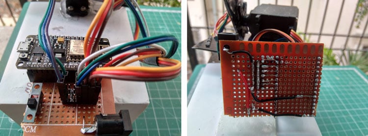
As you see above in the circuit diagram, with some easy steps, make all the connections while making the circuit
Solder female pin on PCB for NodeMCU.
Solder male header for all servo.
Connect each digital pin to the servo control signal pin.
Connect the common ground of all servo and NodeMCU to DC jack GND.
Connect all Vcc of servo and NodeMCU(Vin) pin to Vcc pin of DC jack through a sliding switch.
Complete Project Code
#define BLYNK_PRINT Serial
#include <ESP8266WiFi.h>
#include <BlynkSimpleEsp8266.h>
#include <Servo.h>
Servo servo1;
Servo servo2;
Servo servo3;
Servo servo4;
Servo servo5;
char auth[] = "asCBTcooYXmcpTxrGld8AyXEm6Q7gDKr";
char ssid[] = "udit_accesspoint";
char pass[] = "admin@pass";
void setup()
{
  Serial.begin(9600);
  Blynk.begin(auth, ssid, pass);
  servo1.attach(5); // NodeMCU D1 pin
  servo2.attach(4); // NodeMCU D2 pin
  servo3.attach(0); // NodeMCU D3 pin
  servo4.attach(2); // NodeMCU D4 pin
  servo5.attach(14); // NodeMCU D5 pin
}
void loop()
{
  Blynk.run();
}
BLYNK_WRITE(V1)
{
  servo1.write(param.asInt());
}
BLYNK_WRITE(V2)
{
  servo2.write(param.asInt());
}
BLYNK_WRITE(V3)
{
  servo3.write(param.asInt());
}
BLYNK_WRITE(V4)
{
  servo4.write(param.asInt());
}
BLYNK_WRITE(V5)
{
  servo5.write(param.asInt());
}
