

Robotic Arms have proved themselves useful and more productive in many applications where speed, accuracy and safety is required. But to me, what’s more than that is these things are cool to look at when they work. I have always wished for a robotic arm that could help me with my daily works just like Dum-E and Dum-U that Tony stark uses in his lab. These two bots can be seen helping him while building the Iron man suits or filming his work using a video camera. Actually Dum-E has also saved his life once....... and this is where I would like to stop it because this is no fan Page. Apart from the fictional world there are many cool real world Robotic Arms made by Fanuc, Kuka, Denso, ABB, Yaskawa etc. These robotic arms are used in Production line of automobiles, mining plants, Chemical industries and many other places.
So, in this tutorial we are going to build our own Robotic Arm with the help of Arduino and MG995 Servo motors. The Robot will have a total of 4 Degree of Freedom (DOF) excluding the gripper and can be controlled by a potentiometer. Apart from that we will also program it to have a Record and play feature so that we can record a motion and ask the Robotic Arm to repeat it as many times as we require it. Sounds cool right!!! So lets start building....
Material Required
- Arduino Nano
- 5 MG-995 Servo Motor
- 5-Potentiometer
- Perf Board
- Servo horns
- Nuts and Screws
Note: The body of the robotic arm is completely 3D Printer. If you have a printer you can print them using the given design files. Else, uses the 3D model provided and machine your parts using wood or acrylic. If you don’t have anything then you can just use cardboards to build simple Robotic Arm.
3D Printing and Assembling the Robotic Arm
The most time consuming part in building this robotic Arm is while building its body. Initially I started by designing the body using Solidworks, but later realised that there are many awesome designs readily available on Thingiverse and there is no need to re-invent the wheel. So I went through the designs and found that the Robotic Arm V2.0 by Ashing will work perfectly with our MG995 Servo Motors and would exactly suit our purpose.
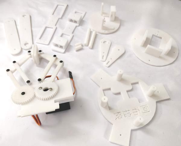
So get to his Thingiverse page (link given above) and download the model files. There are totally 14 parts which has to be printed and the STL files for all of them can be downloaded from Thingiverse page. I used the Cura 3.2.1 Software from Ultimaker to slice the STL files and my TEVO tarantula 3D printer to print them. If you want to know more on 3D printer and how it works you can read this article on Beginners Guide to Getting Started with 3D Printing.
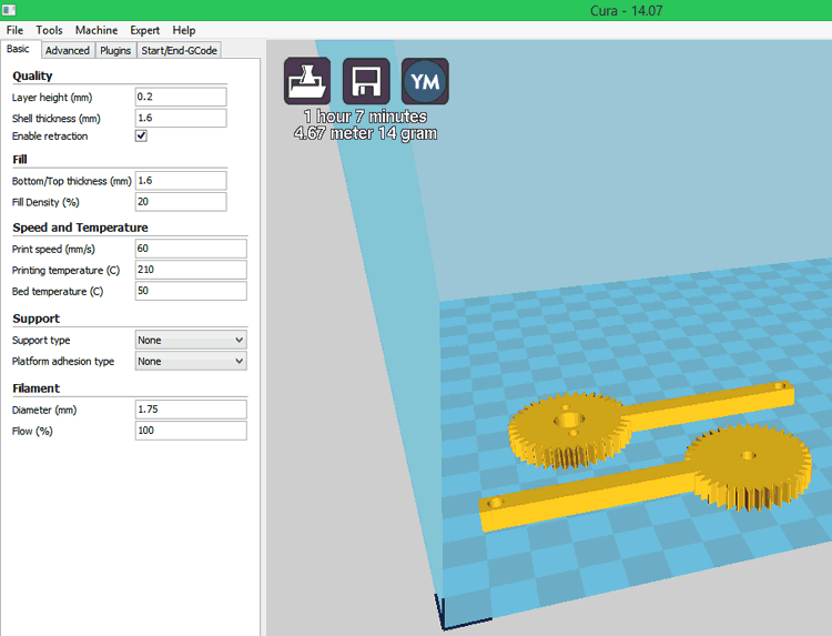
Luckily none of the parts have over hanging structures so supports are not needed. The Design is pretty plain and hence can be easily handled by any basic 3D printer. Approximately after 4.5 hours of printing all the parts are ready to be assembled. The assembly instructions are again neatly explained by Ashing itself and hence I am not going to cover it.
One small tip is that you would have to sand/file the edges of the parts for the motors to fit in. All the motors will fit in vey snug with a little bit of mechanical force. Have patience and use a file to create room for the motors if they seem a bit tight. You would need like 20 numbers of 3mm bolts to assemble the Robotic ARM.
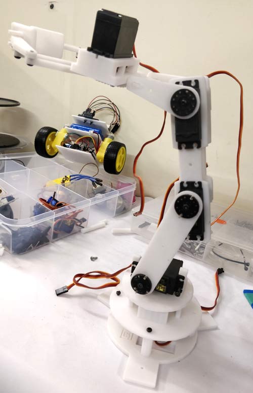
As soon as mounting a motor make sure it can rotate and reach the desired places before screwing it permanently. After assembling, you can proceed with extending the wires of the top three servo motors. I have used the male to female wires to extend them and bring it to circuit board. Make sure you harness the wires properly so that they do not come into your way while the Arm is working. Once assembled my robotic Arm Looked something like this in the picture below.
Circuit Diagram
The MG995 Servo motors operate with 5V and the Arduino board has a 5V regulator with it. So creating the circuit is very easy. We have to connect 5 Servo motors to Arduino PWM pins and 5 Potentiometers to the Arduino Analog pins to control the Servo Motor. The circuit diagram for the same is given below.

For this circuit I have not used any external power source. The Arduino is powered through the USB port and the +5v pin on the board is used to power the potentiometer and the Servo motors. In our Robotic Arm at any given instance of time only one servo motor will be in motion hence the current consumed will be less than 150mA which can be sourced by the on-board voltage regulator of the Arduino Board.
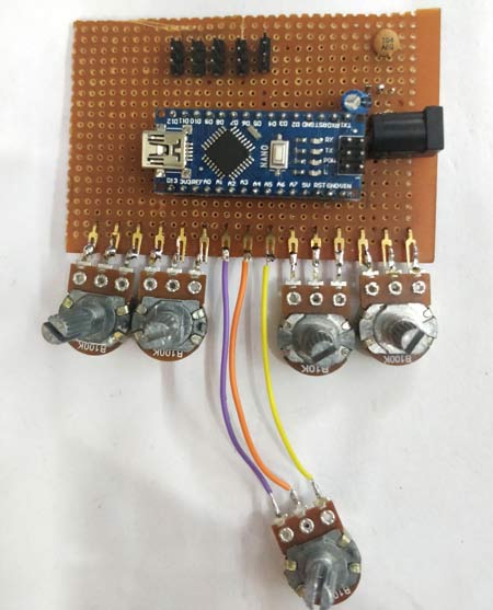
We have 5 Servo motor and 5 potentiometers to control them respectively. These 5 potentiometers are connected to the 5 Analog pins A0 to A4 of the Arduino board. The Servo motors are controlled by PWM signals so we have to connect them to the PWM pins of Arduino. On Arduino Nano the pins D3,D5,D6,D9 and D11 only supports PWM, so we use the first 5 pins for our servo motors. I have used a perf board to solder the connections and my board looked something like this below when completed. I have also added a barrel jack to power the device through battery if required. However it is completely optional.
If you are completely new with Servo motors and Arduino, then you are recommended to read the Basics of Servo motor and Controlling Servo with Arduino article before you proceed with the project.
Programming Arduino for Robotic Arm
Now, the fun part is to program the Arduino to allow the user to record the movements made using the POT and then play it when required. To do this we have to program the Arduino for two modes. Once is the Record mode and the other is the Play mode. The user can toggle between the two modes by using the serial monitor. The complete program to do the same can be found at the bottom of this page, you can use the program as it is. But further below I have explained the program with small snippets for you to understand.
As always we begin the program by adding the required header files. Here the Servo.h header file is used to control the servo motors. We have 5 Servo motors and hence 5 objects are declared giving each motor a name. We also initialise the variables that we will be using in the progam. I have declared them all as global but you can change their scope if you are interested in optimising the program. We have also declared an array called saved_data which as the name states will save all the recorded movements of the Robotic ARM.
#include <Servo.h> //Servo header file
//Declare object for 5 Servo Motors
Servo Servo_0;
Servo Servo_1;
Servo Servo_2;
Servo Servo_3;
Servo Gripper;
//Global Variable Declaration
int S0_pos, S1_pos, S2_pos, S3_pos, G_pos;
int P_S0_pos, P_S1_pos, P_S2_pos, P_S3_pos, P_G_pos;
int C_S0_pos, C_S1_pos, C_S2_pos, C_S3_pos, C_G_pos;
int POT_0,POT_1,POT_2,POT_3,POT_4;
int saved_data[700]; //Array for saving recorded data
int array_index=0;
char incoming = 0;
int action_pos;
int action_servo;
Inside the void setup function we begin the Serial communication at 9600 baud rate. We also specify the pin to which the Servo motors are attached to. Here in our case we have used the pins 3,5,6,9 and 10 which is specified using the attach function. Since the setup function runs during the start-up we can use it to set our Robotic arm in a start position. So I have hardcoded the position value for all five motors. These hardcoded values can be changed according to your preference later. At the end of setup function we print a serial line asking the user to press R or P to do the corresponding action
void setup() {
Serial.begin(9600); //Serial Monitor for Debugging
//Decalre the pins to which the Servo Motors are connected to
Servo_0.attach(3);
Servo_1.attach(5);
Servo_2.attach(6);
Servo_3.attach(9);
Gripper.attach(10);

//Write the servo motors to intial position
Servo_0.write(70);
Servo_1.write(100);
Servo_2.write(110);
Servo_3.write(10);
Gripper.write(10);
Serial.println("Press 'R' to Record and 'P' to play"); //Instrust the user
}
I have defined a function called Read_POT which reads the analog values of all the 5 potentiometers and maps it to the Servo position values. As we know the Arduino has a 8-bit ADC which gives us an output from 0-1023 but the servo motors position values ranges from only 0-180. Also since these servo motors are not very precise it is not safe to drive them to the extreme 0 end or 180 end so we set 10-170 as our limits. We use the map function to convert 0-1023 to 10-170 for all the five motor as shown below.
void Read_POT() //Function to read the Analog value form POT and map it to Servo value
{
   POT_0 = analogRead(A0); POT_1 = analogRead(A1); POT_2 = analogRead(A2); POT_3 = analogRead(A3); POT_4 = analogRead(A4); //Read the Analog values form all five POT
   S0_pos = map(POT_0,0,1024,10,170); //Map it for 1st Servo (Base motor)
   S1_pos = map(POT_1,0,1024,10,170); //Map it for 2nd Servo (Hip motor)
   S2_pos = map(POT_2,0,1024,10,170); //Map it for 3rd Servo (Shoulder motor)
   S3_pos = map(POT_3,0,1024,10,170); //Map it for 4th Servo (Neck motor)
   G_pos  = map(POT_4,0,1024,10,170);  //Map it for 5th Servo (Gripper motor)
}
Recording Mode Code
In the recording mode the user has to control the bot using the Potentiometers. Each POT corresponds to a individual motor, as the pot is varied we should save the position of the motor and the motor number inside the saved_data array. Let’s see how that is achieved using the Record function.
Eliminating Jitter problem with Servo
When working with these Servo motors one common problem that everyone might come across is that the motors might jitter while working. There are many solution for this problem, first you have sort out if the problem is with the control circuitry of the Motor or with the value of position that is written to the servo motor. In my case I used the serial monitor and found that the value of servo_pos is not left constant and sometime jitters up/down randomly.
So I programmed the Arduino to read the POT values twice and compare both the values. The value will be taken as valid only if both the values are same, else the value will be discarded. Thankfully this solved the jitter problem for me. Also make sure that the POT is mounted firmly (I soldered it) to the Analog pin of the Arduino. Any lose connection will also cause jitters. The variables P_x_pos is used to save the old values and then again the x_pos values are read and mapped using the above discussed Read_POT function.
Read_POT(); //Read the POT values  for 1st time
//Save it in a varibale to compare it later
   P_S0_pos = S0_pos;
   P_S1_pos = S1_pos;
   P_S2_pos = S2_pos;
   P_S3_pos = S3_pos;
   P_G_pos  = G_pos;
Read_POT(); //Read the POT value for 2nd time
Now, we have to control the position of the servo motor if the value is valid. Also after controlling we have to save the motor number and motor position in the array. We could have used two different array one for motor number and the other for its position, but to save memory and complexity I have combined both of them by adding a differentiator value to the pos value before saving it in the array.
   if (P_S0_pos == S0_pos) //If 1st and 2nd value are same
   {
    Servo_0.write(S0_pos); //Control the servo

    if (C_S0_pos != S0_pos) //If the POT has been turned
    {
      saved_data[array_index] = S0_pos + 0; //Save the new position to the array. Zero is added for zeroth motor (for understading purpose)
      array_index++; //Increase the array index
    }

    C_S0_pos = S0_pos; //Saved the previous value to check if the POT has been turned
   }
The differentiator value for Sero_0 is 0 and for Servo_1 is 1000 similarly for Servo_3 it is 3000 and for Gripper it is 4000. The lines of code in which the differentiator is added to the value of position and saved to the array is shown below.
saved_data[array_index] = S0_pos + 0; //Save the new position to the array. Zero is added for zeroth motor (for understading purpose)
saved_data[array_index] = S1_pos + 1000; //1000 is added for 1st servo motor as differentiater
saved_data[array_index] = S2_pos + 2000; //2000 is added for 2nd servo motor as differentiater
saved_data[array_index] = S3_pos + 3000; //3000 is added for 3rd servo motor as differentiater
saved_data[array_index] = G_pos + 4000; //4000 is added for 4th servo motor as differentiater
Playing mode Code
After the user has recorded the movements in the saved_data he can toggle to the play mode by entering ‘P” in the serial monitor. Inside the play mode we have access each element saved in the array and split the value to get the motor number and motor position and control their position accordingly.
We use a for loop to navigate through every element of the array the upto the values which are saved in the array. Then we use two variables action_servo and action_pos to get the number of servo motor to be controlled and its position respectively. To get the number of servo motor we have to divide it by 1000 and to get the position we need the last three digits which can be obtained by taking a modulus.
For example if the value saved in the array is 3125, then it means that the 3rd motor has to be moved to the position of 125.
  for (int Play_action=0; Play_action<array_index; Play_action++) //Navigate through every saved element in the array
  {
    action_servo = saved_data[Play_action] / 1000; //The fist charector of the array element is split for knowing the servo number
    action_pos = saved_data[Play_action] % 1000; //The last three charectors of the array element is split to know the servo postion
Now all that is left to do it use the servo number and move it to that obtained value of servo position. I have used a switch case to get into the corresponding servo motor number and the write function to move the servo motor to that position. The switch case is shown below
    switch(action_servo){ //Check which servo motor should be controlled
      case 0: //If zeroth motor
        Servo_0.write(action_pos);
      break;
      case 1://If 1st motor
        Servo_1.write(action_pos);
      break;
      case 2://If 2nd motor
        Servo_2.write(action_pos);
      break;
      case 3://If 3rd motor
        Servo_3.write(action_pos);
      break;
      case 4://If 4th motor
        Gripper.write(action_pos);
      break;
Main loop function
Inside the main loop function, we only have to check what the user has entered through the serial monitor and execute the record mode of the play mode accordingly. The variable incoming is used to hold the value of the user. If ‘R’ is entered Record mode will be activated and if ‘P’ if pressed Play mode will be executed by if conditional statements as shown below.
void loop() {
if (Serial.available() > 1) //If something is recevied from serial monitor
{
incoming = Serial.read();
if (incoming == 'R')
Serial.println("Robotic Arm Recording Started......");
if (incoming == 'P')
Serial.println("Playing Recorded sequence");
}
if (incoming == 'R') //If user has selected Record mode
Record();
if (incoming == 'P') //If user has selected Play Mode
Play();
}
Working of Record and Play Robotic ARM
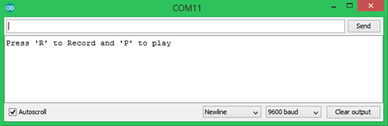
Make the connection as shown in the circuit diagram and upload the code that is given below. Power your Arduino Nano though the USB port of your computer and open the serial monitor you will be welcomed with this intro message.
Now enter R in the serial monitor and press enter. Note that at the bottom of the serial monitor Newline should be selected. Once entered the bot will get into Recording mode and you will the following screen.
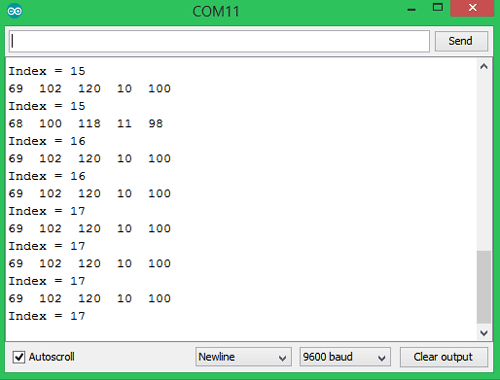
The information shown here can be used for debugging. The numbers starting form 69 are the current position of servo motor 0 to motor 5. The index values are for the array size. Note that the array that we are using has a limit of 700 so we have complete recording the movements before we exceed that limit. After the recording is completed we can enter P in the serial monitor and press enter and we will be taken to the Play mode and the serial monitor will display the following.
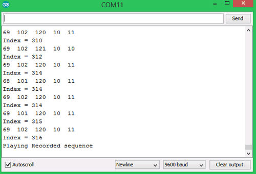
Inside the Play mode the robot will repeat the same movements that were done in the recording mode. These movements will be executed again and again until you interrupt it through the Serial monitor. The complete working can be found at the video linked in the bottom of the page.
Hope you understood the project and enjoyed building it. If you have any problem in getting it to work you can use the comment section below or the forums for more technical help. You can use this bot and build more things on top of it. I am planning to give it some vision using Raspberry Pi and Open CV and check what it can do. What are your ideas? Leave them in the comment section and I will be happy to hear from you.
Complete Project Code
/*
   Robotic ARM with Record and Play option using Arduino
   Code by: B. Aswinth Raj
   Dated: 05-08-2018
*/

#include <Servo.h> //Servo header file
//Declare object for 5 Servo Motors
Servo Servo_0;
Servo Servo_1;
Servo Servo_2;
Servo Servo_3;
Servo Gripper;
//Global Variable Declaration
int S0_pos, S1_pos, S2_pos, S3_pos, G_pos;
int P_S0_pos, P_S1_pos, P_S2_pos, P_S3_pos, P_G_pos;
int C_S0_pos, C_S1_pos, C_S2_pos, C_S3_pos, C_G_pos;
int POT_0,POT_1,POT_2,POT_3,POT_4;
int saved_data[700]; //Array for saving recorded data
int array_index=0;
char incoming = 0;
int action_pos;
int action_servo;
void setup() {
Serial.begin(9600); //Serial Monitor for Debugging
//Declare the pins to which the Servo Motors are connected to
Servo_0.attach(3);
Servo_1.attach(5);
Servo_2.attach(6);
Servo_3.attach(9);
Gripper.attach(10);
//Write the servo motors to initial position
Servo_0.write(70);
Servo_1.write(100);
Servo_2.write(110);
Servo_3.write(10);
Gripper.write(10);
Serial.println("Press 'R' to Record and 'P' to play"); //Instruct the user
}
void Read_POT() //Function to read the Analog value form POT and map it to Servo value
{
   POT_0 = analogRead(A0); POT_1 = analogRead(A1); POT_2 = analogRead(A2); POT_3 = analogRead(A3); POT_4 = analogRead(A4); //Read the Analog values form all five POT
   S0_pos = map(POT_0,0,1024,10,170); //Map it for 1st Servo (Base motor)
   S1_pos = map(POT_1,0,1024,10,170); //Map it for 2nd Servo (Hip motor)
   S2_pos = map(POT_2,0,1024,10,170); //Map it for 3rd Servo (Shoulder motor)
   S3_pos = map(POT_3,0,1024,10,170); //Map it for 4th Servo (Neck motor)
   G_pos  = map(POT_4,0,1024,10,170);  //Map it for 5th Servo (Gripper motor)
}
void Record() //Function to Record the movements of the Robotic Arm
{
Read_POT(); //Read the POT values  for 1st time
//Save it in a variable to compare it later
   P_S0_pos = S0_pos;
   P_S1_pos = S1_pos;
   P_S2_pos = S2_pos;
   P_S3_pos = S3_pos;
   P_G_pos  = G_pos;

Read_POT(); //Read the POT value for 2nd time

   if (P_S0_pos == S0_pos) //If 1st and 2nd value are same
   {
    Servo_0.write(S0_pos); //Control the servo

    if (C_S0_pos != S0_pos) //If the POT has been turned
    {
      saved_data[array_index] = S0_pos + 0; //Save the new position to the array. Zero is added for zeroth motor (for understading purpose)
      array_index++; //Increase the array index
    }

    C_S0_pos = S0_pos; //Saved the previous value to check if the POT has been turned
   }
//Similarly repeat for all 5 servo Motors
   if (P_S1_pos == S1_pos)
   {
    Servo_1.write(S1_pos);

    if (C_S1_pos != S1_pos)
    {
      saved_data[array_index] = S1_pos + 1000; //1000 is added for 1st servo motor as differentiator
      array_index++;
    }

    C_S1_pos = S1_pos;
   }
   if (P_S2_pos == S2_pos)
   {
    Servo_2.write(S2_pos);

    if (C_S2_pos != S2_pos)
    {
      saved_data[array_index] = S2_pos + 2000; //2000 is added for 2nd servo motor as differentiator
      array_index++;
    }

    C_S2_pos = S2_pos;
   }
   if (P_S3_pos == S3_pos)
   {
    Servo_3.write(S3_pos);

    if (C_S3_pos != S3_pos)
    {
      saved_data[array_index] = S3_pos + 3000; //3000 is added for 3rd servo motor as differentiater
      array_index++;
    }

    C_S3_pos = S3_pos;
   }
   if (P_G_pos == G_pos)
   {
    Gripper.write(G_pos);

    if (C_G_pos != G_pos)
    {
      saved_data[array_index] = G_pos + 4000; //4000 is added for 4th servo motor as differentiator
      array_index++;
    }

    C_G_pos = G_pos;
   }

  //Print the value for debugging
  Serial.print(S0_pos);  Serial.print("  "); Serial.print(S1_pos); Serial.print("  "); Serial.print(S2_pos); Serial.print("  "); Serial.print(S3_pos); Serial.print("  "); Serial.println(G_pos);
  Serial.print ("Index = "); Serial.println (array_index);
  delay(100);
}

void Play() //Functon to play the recorded movements on the Robotic ARM
{
  for (int Play_action=0; Play_action<array_index; Play_action++) //Navigate through every saved element in the array
  {
    action_servo = saved_data[Play_action] / 1000; //The fist character of the array element is split for knowing the servo number
    action_pos = saved_data[Play_action] % 1000; //The last three characters of the array element is split to know the servo postion
    switch(action_servo){ //Check which servo motor should be controlled
      case 0: //If zeroth motor
        Servo_0.write(action_pos);
      break;
      case 1://If 1st motor
        Servo_1.write(action_pos);
      break;
      case 2://If 2nd motor
        Servo_2.write(action_pos);
      break;
      case 3://If 3rd motor
        Servo_3.write(action_pos);
      break;
      case 4://If 4th motor
        Gripper.write(action_pos);
      break;
    }
    delay(50);

  }
}

void loop() {
if (Serial.available() > 1) //If something is received from serial monitor
{
incoming = Serial.read();
if (incoming == 'R')
Serial.println("Robotic Arm Recording Started......");
if (incoming == 'P')
Serial.println("Playing Recorded sequence");
}
if (incoming == 'R') //If user has selected Record mode
Record();
if (incoming == 'P') //If user has selected Play Mode
Play();
}
Comments
Hello,
Can I ask you to post again the instructions for building the arm ?
For some reason, Ashing's site doesn't work.
Thank you and have a great day!
Very good

Hello,
I tired running the code ,I am getting this error .So can u plzz fix this.
Sketch uses 4934 bytes (16%) of program storage space. Maximum is 30720 bytes.
Global variables use 1798 bytes (87%) of dynamic memory, leaving 250 bytes for local variables. Maximum is 2048 bytes.
Low memory available, stability problems may occur.