
Robotic Arms, are one of the fascinating engineering creations and it is always fascinating to watch these things tilt and pan to get complex things done just like a human arm would. These robotic arms can be commonly found in industries at the assembly line performing intense mechanical work like welding, drilling, painting etc, recently advanced robotic arms with high precision are also being developed to perform complex surgical operations. So in this tutorial let’s build a simple Robotic Arm using ARM7-LPC2148 microcontroller for picking & placing an object by manual controlling few potentiometers.
In this tutorial we will use a 3D printed robotic ARM that was built by following the procedure in thingiverse. The ARM uses 4 servo motor for robotic ARM movement. If you do not have a printer, you can also build your arm with simple cardboards like we built for our Arduino Robotic Arm Project. For inspiration you can also refer to the Record and Play Robotic Arm that we built earlier using Arduino.
So now let’s get the things ready for our project
Components Required
- 3D Printer Robotic ARM
- ARM7-LPC2148
- SG-90 Servo Motor (4)
- 10k Potentiometer (4)
- Push Button (4)
- LED (4)
- 5V (1A) DC Power Adapter
- Resistors (10k (4), 2.2k(4))
- Breadboard
- Connecting Wires
Getting ready the 3D printed Robotic ARM
The 3D printed Robotic Arm used in this tutorial was made by following the design given by EEZYbotARM which is available in the Thingiverse. The complete procedure for making the 3D printed robotic arm and the assembling detail with video are present in the thingiverse link, which is share above.

This is the image of my 3D printed Robotic Arm after assembling with 4 Servo Motors.
Circuit Diagram
The following image shows the circuit connections of ARM based Robotic Arm.

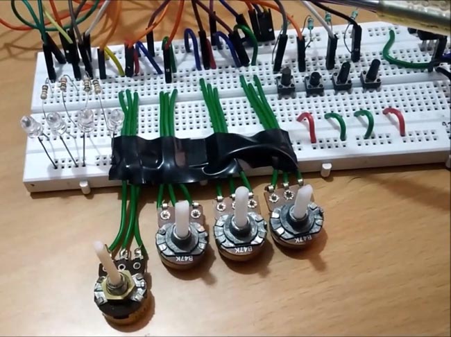
The circuit connections for the project is simple. Make sure to power the Servo Motors with a separate 5V DC power adapter. For potentiometers and push buttons we can use 3.3V available from the LPC2148 microcontroller.
Here we are using the 4 ADC pins of LPC2148 with 4 potentiometers. And also 4 PWM pins of LPC2148 connected with the PWM pins of the servo motor. We have also connected 4 push buttons to select which motor to operate. So, after pressing the button respected potentiometer is varied to change the position of the servo motor.
The push buttons one end that is connected with GPIO of LPC2148 are pull-down via resistor of 10k and another end is connected with 3.3V. Also 4 LEDs are connected to indicate which servo motor is selected to change the position.
Circuit connections between 4 Servo Motor & LPC2148:
| LPC2148 | Servo Motor |
| P0.1 | SERVO1 (PWM-Orange) |
| P0.7 | SERVO2 (PWM-Orange) |
| P0.8 | SERVO3 (PWM-Orange) |
| P0.21 | SERVO4 (PWM-Orange) |
Circuit connections between 4 Potentiometer & LPC2148:
| LPC2148 | Potentiometer Centre Pin Left Pin – 0V GND of LPC2148 Right Pin – 3.3V of LPC2148 |
| P0.25 | Potentiometer1 |
| P0.28 | Potentiometer2 |
| P0.29 | Potentiometer3 |
| P0.30 | Potentiometer4 |
Circuit connections of 4 LED’s with LPC2148:
| LPC2148 | LED Anode (Cathode of all LED is GND) |
| P1.28 | LED1 (Anode) |
| P1.29 | LED2 (Anode) |
| P1.30 | LED3 (Anode) |
| P1.31 | LED4 (Anode) |
Circuit connections of 4 push buttons with LPC2148:
| LPC2148 | Push Button (With Pull-Down Resistor 10k) |
| P1.17 | Pushbutton1 |
| P1.18 | Pushbutton2 |
| P1.19 | Pushbutton3 |
| P1.20 | Pushbutton4 |
Steps involved in Programming LPC2148 for Robotic Arm
Before programming for this Robotic Arm, we need to know about generating PWM in LPC2148 and using ADC in ARM7-LPC2148. For that, refer our previous projects on Interfacing Servo motor with LPC2148 and how to use ADC in LPC2148.
ADC conversion using LPC2148
As we need to provide ADC values for setting duty cycle value for generating PWM output for controlling servo Motor position. We need to find ADC values of the potentiometer. As we have four potentiometers for controlling four Servo motor, we need 4 ADC channel of LPC2148. Here in this tutorial we are using ADC pins (P0.25, P0.28, P0.29, P0.30) of ADC channels of 4,1,2,3 respectively present in LPC2148.
Generating PWM signals for Servo Motor using LPC2148
As we need to generate PWM signals for controlling servo motor position. We need to set the duty cycle of PWM. We have four Servo motors connected to the robotic arm so we need 4 PWM channel of LPC2148. Here in this tutorial we are using PWM pins (P0.1, P0.7, P0.8, P0.21) of PWM channels of 3,2,4,5 respectively present in LPC2148.
Programming and Flashing Hex File to LPC2148
To Program ARM7-LPC2148 we need keil uVision & to flash HEX code to LPC2148 Flash Magic tool is needed. A USB Cable is used here to program ARM7 Stick via micro USB port. We write code using Keil and create a hex file and then the HEX file is flashed to ARM7 stick using Flash Magic. To know more about installing keil uVision and Flash Magic and how to use them follow the link Getting Started With ARM7 LPC2148 Microcontroller and Program it using Keil uVision.
Coding Explanation
Complete program for this Robotic Arm Project is given at the end of the tutorial. Now let’s see the programming in detail.
Configuring PORT of LPC2148 for using GPIO, PWM and ADC:
Using the PINSEL1 register to enable the ADC channels- ADC0.4, ADC0.1, ADC0.2, ADC0.3 for the pins P0.25, P0.28, P0.29, P0.30. And also, for PWM5 for the pin P0.21 (1<<10).
#define AD04 (1<<18) //Select AD0.4 function for P0.25
#define AD01 (1<<24) //Select AD0.1 function for P0.28
#define AD02 (1<<26) //Select AD0.2 function for P0.29
#define AD03 (1<<28) //Select AD0.3 function for P0.30

PINSEL1 |= AD04 | AD01 | AD02 | AD03 | (1<<10);
Using the PINSEL0 register to enable the PWM channels PWM3, PWM2, PWM4 for pins P0.1, P0.7, P0.8 of LPC2148.
PINSEL0 = 0x000A800A;
Using the PINSEL2 register to enable the GPIO pin function for all the pins in PORT1 used for the connection of LED and pushbutton.
PINSEL2 = 0x00000000;
To make the LED pins as Output and Pushbutton pins as Input the IODIR1 register is used. (0 for INPUT & 1 for OUTPUT)
IODIR1 = ((0<<17)|(0<<18)|(0<<19)|(0<<20)|(1<<28)|(1<<29)|(1<<30)|(1<<31));
While the pin numbers are defined as
#define SwitchPinNumber1 17   // (Connected with P1.17)
#define SwitchPinNumber2 18   // (Connected with P1.18)
#define SwitchPinNumber3 19   // (Connected with P1.19)
#define SwitchPinNumber4 20   // (Connected with P1.20)

#define LedPinNumber1    28    // (Connected with P1.28)
#define LedPinNumber2    29    // (Connected with P1.29)
#define LedPinNumber3    30    // (Connected with P1.30)
#define LedPinNumber4    31    // (Connected with P1.31)
Configuring ADC conversion setting
Next the ADC conversion mode and the clock for ADC is set using the AD0CR_setup register.
unsigned long AD0CR_setup = (CLKDIV<<8) | BURST_MODE_OFF | PowerUP; //Setting up ADC Mode
While the CLCKDIV, Burst Mode and PowerUP are defined as
#define CLKDIV (15-1)
#define BURST_MODE_OFF (0<<16)              // 1 for on and 0 for off
#define PowerUP (1<<21)
Setting the clock for ADC Conversion (CLKDIV)
This is used to produce the clock for ADC. 4Mhz ADC clock (ADC_CLOCK=PCLK/CLKDIV) where "CLKDIV-1" is actually used, in our case PCLK=60mhz
Burst Mode (Bit-16): This bit is used for BURST conversion. If this bit is set the ADC module will do the conversion for all the channels that are selected (SET) in SEL bits. Setting 0 in this bit will disable the BURST conversion.
Power Down Mode (Bit-21): This is used for turning ADC ON or OFF. Setting (1) in this bit brings ADC out of power down mode and makes it operational. Clearing this bit will power down the ADC.
Configuring PWM conversion setting
First Reset and disable counter for PWM using PWMTCR register and setup the PWM Timer Prescale Register with prescaler value.
PWMTCR = 0x02;
PWMPR =  0x1D;
Next set the maximum number of counts in one cycle. This is done in Match Register 0 (PWMMR0). As we have 20000 as it is a PWM wave of 20msecs
PWMMR0 = 20000;
After that set the value for duty cycle in the match registers, we are using PWMMR4, PWMMR2, PWMMR3, PWMMR5. Here we are setting initial values of 0 msec (Toff)
PWMMR4 = 0;
PWMMR2 = 0;
PWMMR3 = 0;
PWMMR5 = 0;
After that set the PWM Match Control Register to cause a counter reset when the match register occurs.
PWMMCR = 0x00000002; // Reset on MR0 match
After that, the PWM latch Enable Register to enable the use of match value (PWMLER)
PWMLER = 0x7C; // Latch enable for PWM2,PWM4,PWM4 and PWM5
Reset the timer counter using a bit in the PWM Timer Control Register (PWMTCR) and also it enables the PWM.
PWMTCR = 0x09; // Enable PWM and counter
Next enable the PWM outputs and set the PWM in single edge-controlled mode in PWM control register (PWMPCR).
PWMPCR = 0x7C00; // Enable PWM2,PWM4,PWM4 and PWM5, single edge controlled PWM
Selecting the Servo Motor to rotate using Push buttons
We have four push buttons which is used to rotate four different servo motors. By selecting one push button and varying the corresponding potentiometer, ADC value sets the duty cycle and corresponding servo motor changes its position. To get the status of the push button switch
switchStatus1 = (IOPIN1>>SwitchPinNumber1) & 0x01 ;
So, by depending upon which switch value is HIGH the ADC conversion takes places and then after successful conversion of the ADC (0 to 1023) value, it is mapped in terms of (0 to 2045) and then the duty cycle value is written to the (PWMMRx) PWM pin connected to servo motor. And also, a LED is turned HIGH for indicating which switch is pressed. The following is an example for the first push button
if(switchStatus1 == 1)
        {
         IOPIN1 = (1<<LedPinNumber1);             //Make LED1 HIGH
         AD0CR =  AD0CR_setup | SEL_AD01;         //Setup ADC for channel 1
         AD0CR |= START_NOW;                      //Start new Conversion at ADC1
          while( (AD0DR1 & ADC_DONE) == 0 )        //Check for ADC conversion
         {
          convert1 = (AD0DR1>>6) & 0x3ff;         //Get ADC value
          result1 = map(convert1,0,1023,0,2450);  //Convert ADC values in terms of dutycyle for PWM
          PWMMR5 = result1;                                   //Set Duty Cylce value to PWM5
          PWMLER = 0x20;                          //Enable PWM5
  delay_ms(2);
      }
}
     else
      {
         IOPIN1 = (0<<LedPinNumber1);             //Set LED1 LOW
       }
Working of Pick and Place Robotic Arm
After uploading code to the LPC2148, press any switch and vary the corresponding potentiometer to change the position of the robotic arm.
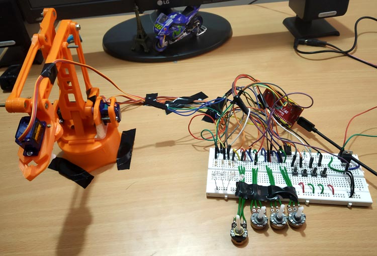
Each switch and potentiometer control each servomotor movement that is base left or right movement, up or down movement, forward or backward and then the gripper to hold and release movement. Complete code with a detailed working video is given below.
Complete Project Code
//Robotic ARM using LPC2148
//Code by Circuit Digest

#include <lpc214x.h>
#include <stdint.h>

#define SwitchPinNumber1 17
#define SwitchPinNumber2 18
#define SwitchPinNumber3 19
#define SwitchPinNumber4 20

#define LedPinNumber1    28
#define LedPinNumber2    29
#define LedPinNumber3    30
#define LedPinNumber4    31

#define AD04 (1<<18) //Select AD0.4 function for P0.25
#define AD01 (1<<24) //Select AD0.1 function for P0.28
#define AD02 (1<<26) //Select AD0.2 function for P0.29
#define AD03 (1<<28) //Select AD0.3 function for P0.30

#define SEL_AD04 (1<<4) //Select ADC channel 4
#define SEL_AD01 (1<<1) //Select ADC channel 1
#define SEL_AD02 (1<<2) //Select ADC channel 2
#define SEL_AD03 (1<<3) //Select ADC channel 3

#define CLKDIV (15-1)    // 4Mhz ADC clock (ADC_CLOCK=PCLK/CLKDIV) where "CLKDIV-1" is actually used , in our case PCLK=60mhz
#define BURST_MODE_OFF (0<<16)           // 1 for on and 0 for off
#define PowerUP (1<<21)
#define START_NOW ((0<<26)|(0<<25)|(1<<24))   //001 for starting the conversion immediately
#define ADC_DONE (1UL<<31)
#define VREF 3.3                            //Reference Voltage at VREF Pin

volatile int result1=0;
volatile int result2=0;
volatile int result3=0;
volatile int result4=0;

volatile int convert1=0;
volatile int convert2=0;
volatile int convert3=0;
volatile int convert4=0;

volatile unsigned int  switchStatus1;
volatile unsigned int  switchStatus2;
volatile unsigned int  switchStatus3;
volatile unsigned int  switchStatus4;

long map(long x, long in_min, long in_max, long out_min, long out_max)  // Map function to convert range
{
  return (x - in_min) * (out_max - out_min) / (in_max - in_min) + out_min;
}

void delay_ms(uint16_t j)      /* loop to generate 1 milisecond delay with Cclk = 60MHz */
{
    uint16_t x,i;

                for(i=0;i<j;i++)
                {
    for(x=0; x<6000; x++);
                }
}

int main()
{

    PINSEL0 = 0x000A800A;   // Configure P0.1,P0.7,P0.8 as PWM3,PWM2,PWM4 pins
    PINSEL2 = 0x00000000;   //Configure the PORT1 Pins as GPIO;
   PINSEL1 |= AD04 | AD01 | AD02 | AD03 | (1<<10); // Configure P0.25,P0.28,P0.29,P0.30 as ADC0.4,   ADC0.1, ADC0.2, ADC0.3 Pins & P0.21 as PWM5
   IODIR1 = ((0<<17)|(0<<18)|(0<<19)|(0<<20)|(1<<28)|(1<<29)|(1<<30)|(1<<31)); //Configure LED pin as output and Switch Pin as input
    unsigned long AD0CR_setup = (CLKDIV<<8) | BURST_MODE_OFF | PowerUP; //Setting up ADC Mode
     PWMTCR = 0x02;          // Reset and disable counter for PWM
     PWMPR =  0x1D;          // Prescale Register value
     PWMMR0 = 20000;         // Time period of PWM wave, 20msec
     PWMMR4 = 0;                          // Initial values of PWM wave 0 msec
     PWMMR2 = 0;
     PWMMR3 = 0;
     PWMMR5 = 0;
     PWMMCR = 0x00000002;           // Reset on MR0 match
     PWMLER = 0x7C;                 // Latch enable for PWM2,PWM4,PWM4 and PWM5
     PWMPCR = 0x7C00;         // Enable PWM2,PWM4,PWM4 and PWM5, single edge controlled PWM
     PWMTCR = 0x09;                 // Enable PWM and counter


while(1)
    {

       switchStatus1 = (IOPIN1>>SwitchPinNumber1) & 0x01 ;  // Read the switch status
       switchStatus2 = (IOPIN1>>SwitchPinNumber2) & 0x01 ;  // Read the switch status
       switchStatus3 = (IOPIN1>>SwitchPinNumber3) & 0x01 ;  // Read the switch status
       switchStatus4 = (IOPIN1>>SwitchPinNumber4) & 0x01 ;  // Read the switch status

if(switchStatus1 == 1)                      //Turn ON/OFF LEDs depending on switch status and start ADC conversion
        {
                       IOPIN1 = (1<<LedPinNumber1);                  //Make LED1 HIGH
                       AD0CR =  AD0CR_setup | SEL_AD01;         //Setup ADC for channel 1
                       AD0CR |= START_NOW;                               //Start new Conversion at ADC1

                       while( (AD0DR1 & ADC_DONE) == 0 )        //Check for ADC conversion
                  {
                             convert1 = (AD0DR1>>6) & 0x3ff;         //Get ADC value
                              result1 = map(convert1,0,1023,0,2450);  //Convert ADC values in terms of dutycyle for PWM
                              PWMMR5 = result1;                               //Set Duty Cylce value to PWM5
                              PWMLER = 0x20;                          //Enable PWM5
                               delay_ms(2);
                 }
        }
      else
         {
         IOPIN1 = (0<<LedPinNumber1);             //Set LED1 LOW
         }

if(switchStatus2 == 1)                      //Turn ON/OFF LEDs depending on switch status and start ADC conversion
       {
                 IOPIN1 = (1<<LedPinNumber2);             //Make LED2 HIGH
                 AD0CR =  AD0CR_setup | SEL_AD02;         //Setup ADC for channel 2
                 AD0CR |= START_NOW;                      //Start new Conversion at ADC2

while( (AD0DR2 & ADC_DONE) == 0 )        //Check for ADC conversion
        {
                     convert2 = (AD0DR2>>6) & 0x3ff;        //Get ADC value
                      result2 = map(convert2,0,1023,0,2450); //Convert ADC values in terms of dutycyle for PWM
                      PWMMR4 = result2;                      //Set Duty Cylce value to PWM4
                      PWMLER = 0x10;                         //Enable PWM4
                      delay_ms(2);
         }
   }  else
            {
                      IOPIN1 = (0<<LedPinNumber2);              //Set LED2 LOW
            }

if(switchStatus3 == 1)                       //Turn ON/OFF LEDs depending on switch status and start ADC conversion
        {
                     IOPIN1 = (1<<LedPinNumber3);              //Set LED3 HIGH                                                                                 AD0CR =  AD0CR_setup | SEL_AD03;          //Setup ADC for channel 3
                     AD0CR |= START_NOW;                       //Start new Conversion at ADC3
                     while( (AD0DR3 & ADC_DONE) == 0 )         //Check for ADC conversion
                         {
                           convert3 = (AD0DR3>>6) & 0x3ff;         //Get ADC value
                           result3 = map(convert3,0,1023,0,2450);  //Convert ADC values in terms of dutycyle for PWM
                           PWMMR3 = result3;                                 //Set Duty Cylce value to PWM3
                           PWMLER = 0x08;                          //Enable PWM3
                            delay_ms(2);
                              }
     } else
       {
         IOPIN1 = (0<<LedPinNumber3);              //Set LED4 LOW
       }
 if(switchStatus4 == 1)                      //Turn ON/OFF LEDs depending on switch status and start ADC conversion
       {
                           IOPIN1 = (1<<LedPinNumber4);              //Set LED4 HIGH
                           AD0CR =  AD0CR_setup | SEL_AD04;          //Setup ADC for channel 4
                           AD0CR |= START_NOW;                       //Start new Conversion at ADC4
                          while( (AD0DR4 & ADC_DONE) == 0 )         //Check for ADC conversion
                             {
                            convert4 = (AD0DR4>>6) & 0x3ff;           //Get ADC value
                            result4 = map(convert4,0,1023,0,2450);    //Convert ADC values in terms of dutycyle for PWM
                             PWMMR2 = result4;                         //Set Duty Cylce value to PWM                                                                PWMLER = 0x04;                            //Enable PWM2
                             delay_ms(2);
                        }
        } else
                        {
                                IOPIN1 = (0<<LedPinNumber4);          //Set LED4 LOW
                        }
         }
      }

Explanation about this concept and GPIO pin description is excellent.. can you kindly provide me a HEX file for the above experiment.it will be very useful for us to do .