
In our previous tutorial, we have interfaced stepper motor with ARM7-LPC2148. In this tutorial, we will control Servo Motor with ARM7-LPC2148. Servo motor has low power consumption advantage over stepper motor. A servo motor stops its power consumption when the desired position is reached but the stepper motor continuous to consume power to lock up the shaft in desired position. Servo motors are mostly used in Robotics Projects because of their accuracy and easy handling.
In this tutorial we will learn about Servo Motor and How to interface Servo with ARM7-LPC2148. A potentiometer is also interfaced to vary the position of the servo motor’s shaft, and a LCD to display the angle value.
Servo Motor
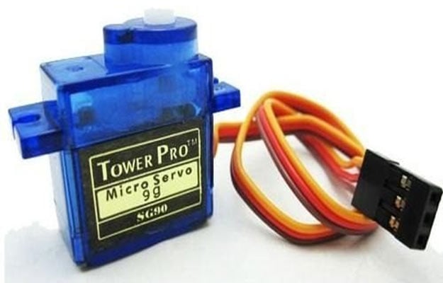
A Servo Motor is a combination of DC motor, position control system and gears. Servo motor’s rotation is controlled by applying a PWM signal to it, width of the PWM signal decides the rotation angle and direction of the motor. Here we will be using SG90 Servo Motor in this tutorial, it is one of the popular and cheapest one. SG90 is a 180 degree servo. So with this servo we can position the axis from 0-180 degrees:
- Operating Voltage: +5V
- Gear Type: Plastic
- Rotation Angle: 0 to 180 deg
- Weight: 9gm
- Torque: 2.5kg/cm
Before we can start programming for the Servo motor we should know what type of signal is to be sent for controlling the Servo motor. We should program the MCU to send PWM signals to the signal wire of the Servo motor. There is a control circuitry inside the servo motor which reads the duty cycle of the PWM signal and positions the servo motors shaft in the respective place as shown in the picture below
For every 20 milliseconds Servo motor checks the pulse. So, adjust the pulse width of the signal to rotate the motor’s shaft.
- 1 ms (1 millisecond) pulse width for rotation of servo to 0 degree
- 1.5ms pulse width for rotation to 90 degree (neutral position)
- 2 ms pulse width for rotation of servo to 180 degree.
Before Connecting Servo to ARM7-LPC2148, you can test your servo with the help of this Servo Motor Tester Circuit. Also check how a servo motor can be interfaced with other Microcontrollers:
- Servo Motor Control using Arduino
- Servo Motor Interfacing with 8051 Microcontroller
- Servo Motor Control using MATLAB
- Servo Motor Control with Raspberry Pi
- Interfacing Servo Motor with MSP430G2
- Interfacing Servo Motor with STM32F103C8
Controlling Servo Motor using LPC2148 PWM & ADC
A Servo Motor can be controlled by LPC2148 using PWM. By providing PWM signal to SERVO’S PWM pin with a period of 20ms and frequency of 50Hz we can position the shaft of servo motor around 180 degrees (-90 to +90).
A Potentiometer is used to vary the duty cycle of PWM signal and rotate the servo motor’s shaft, this method is implemented by using the ADC module in LPC2148. So we need both PWM and ADC concepts to be implemented in this tutorial. So kindly refer our previous tutorials to learn PWM and ADC in ARM7-LPC2148.
PWM & ADC pins in ARM7-LPC2148
The image below shows the PWM and ADC pins in LPC2148. Yellow boxes indicate the (6) PWM pins and black box indicates the (14) ADC pins.

Components Required
Hardware
- ARM7-LPC2148
- LCD (16x2) Display Module
- Servo Motor (SG-90)
- 3.3V voltage regulator
- 10k Potentiometer (2 Nos)
- Breadboard
- Connecting Wires
Software
- Keil uVision5
- Flash Magic Tool
Circuit Diagram and Connections

The table below shows the Connection between Servo Motor & ARM7-LPC2148:
SERVO PINS | ARM7-LPC2148 |
RED (+5V) | +5V |
BROWN (GND) | GND |
ORANGE (PWM) | P0.1 |
The pin P0.1 is the PWM output of LPC2148.
The table below shows the circuit connections between LCD & ARM7-LPC2148.
ARM7-LPC2148 | LCD (16x2) |
P0.4 | RS (Register Select) |
P0.6 | E (Enable) |
P0.12 | D4 (Data pin 4) |
P0.13 | D5(Data pin 5) |
P0.14 | D6(Data pin 6) |
P0.15 | D7 (Data pin 7) |
GND | VSS, R/W, K |
+5V | VDD, A |
The table below shows the connections between ARM7 LPC2148 & potentiometer with 3.3V voltage regulator.
3.3V Voltage Regulator IC | Pin function | ARM-7 LPC2148 Pin |
1.Left Pin | - Ve from GND
| GND pin |
2.Centre Pin | Regulated +3.3V Output
| To potentiometer Input and potentiometer’s output to P0.28 of LPC2148 |
3.Right Pin | + Ve from 5V INPUT | +5V |
Points to be Noted
1. A voltage regulator of 3.3V is used here to provide analog input value to the ADC pin (P0.28) of LPC2148. As we are using 5V power we need to regulate voltage with voltage regulator of 3.3V.
2. A Potentiometer is used to vary voltage between (0V to 3.3V) to provide analog input (ADC) to LPC2148 pin P0.28
3. The pin P0.1 of LPC2148 provides PWM output to the servo motor to control the position of the motor.
4. According to the analog input (ADC) value the position of the servo motor changes from (0 to 180 degree) through PWM output pin at P0.1 of LPC2148.
Programming ARM7-LPC2148 for Servo Motor Control
To Program ARM7-LPC2148 we need keil uVision & Flash Magic tool. We are using USB Cable to program ARM7 Stick via micro USB port. We write code using Keil and create a hex file and then the HEX file is flashed to ARM7 stick using Flash Magic. To know more about installing keil uVision and Flash Magic and how to use them follow the link Getting Started With ARM7 LPC2148 Microcontroller and Program it using Keil uVision.
Steps involved in configuring LPC2148 for PWM & ADC to control the Servo Motor
Step 1:- Include the necessary header files for coding LPC2148
#include <lpc214x.h>
#include<stdint.h>
#include <stdio.h>
#include <string.h>
Step 2:- Next thing is to configure the PLL for clock generation as it sets the system clock and peripheral clock of LPC2148 as per programmers need. The maximum clock frequency for LPC2148 is 60Mhz. Following lines are used to configure PLL clock generation.
void initilizePLL (void)     //Function to use PLL for clock generation
{
  PLL0CON = 0x01;
  PLL0CFG = 0x24;
  PLL0FEED = 0xAA;
  PLL0FEED = 0x55;
  while(!(PLL0STAT & 0x00000400));
  PLL0CON = 0x03;
  PLL0FEED = 0xAA;
  PLL0FEED = 0x55;
  VPBDIV = 0x01;
}
Step 3:- Next thing to do is select the PWM pins and PWM function of LPC2148 by using PINSEL register. We use PINSEL0 as we use P0.1 for PWM output of LPC2148.
PINSEL0 |= 0x00000008; // Setting pin P0.1 of LPC2148 as PWM3
Step 4:- Next, we need to RESET the timers using PWMTCR (Timer Control Register).
PWMTCR = 0x02; // Reset and disable counter for PWM
And then next set the prescale value which decides the resolution of PWM is set.
PWMPR = 0x1D; // Prescale Register value
Step 5:- Next, set the PWMMCR (PWM match control register) as it sets operation like reset, interrupts for PWMMR0 and PWMMR3.
PWMMCR = 0x00000203; // Reset and interrupt on MR0 match, interrupt on MR3 match
Step 6:- The maximum period of the PWM channel is set using PWMMR0 and the Ton of the PWM duty cycle is initially set to 0.65msec
PWMMR0 = 20000;                                // Time period of PWM wave, 20msec
PWMMR3 = 650;                                             // Ton of PWM wave 0.65 msec
Step 7:- Next, we need to set the Latch Enable to the corresponding match registers using PWMLER
PWMLER = 0x09; // Latch enable for PWM3 and PWM0
(We use PWMMR0 & PWMMR3) So enable the corresponding bit by setting 1 in PWMLER
Step 8:- To enable the PWM output to the pin we need to use the PWMTCR for enabling the PWM Timer counters and PWM modes.
PWMPCR = 0x0800;                                // Enable PWM3 and PWM 0, single edge controlled PWM
PWMTCR = 0x09;                                             // Enable PWM and counter
Step 9:- Now we need to get the potentiometer values for setting duty cycle of PWM from ADC pin P0.28. So, we use ADC module in LPC2148 for converting potentiometers analog input (0 to 3.3V) to the ADC values (0 to 1023).
Step 10:- For selecting ADC pin P0.28 in LPC2148, we use
PINSEL1 = 0x01000000;           //Setting P0.28 as ADC INPUT
AD0CR = (((14)<<8) | (1<<21)); //Setting clock and PDN for A/D Conversion
The following lines capture the Analog input (0 to 3.3V) and convert it into digital value (0 to 1023). And then this digital values are divided by 4 to convert them into (0 to 255) and finally fed as PWM output in P0.1 pin of LPC2148. Here we are converting the values from 0-1023 to 0-255 by dividing it with 4 as PWM of LPC2148 has 8-Bit resolution (28).
AD0CR |= (1<<1);                   //Select AD0.1 channel in ADC register
delaytime(10);
AD0CR |= (1<<24);                  //Start the A/D conversion
while( (AD0DR1 & (1<<31)) == 0 );  //Check the DONE bit in ADC Data register
adcvalue = (AD0DR1>>6) & 0x3ff;     //Get the RESULT from ADC data register
dutycycle = adcvalue/4;             //formula to get dutycycle values from (0 to 255)
PWMMR1 = dutycycle;                 //set dutycycle value to PWM match register
PWMLER |= (1<<1);                        //Enable PWM output with dutycycle value
Step 11:- Next, we display those values in the LCD (16X2) Display module. So we add the following lines to initializes LCD display module
Void LCD_INITILIZE(void)          //Function to get ready the LCD
{
IO0DIR = 0x0000FFF0; //Sets pin P0.12,P0.13,P0.14,P0.15,P0.4,P0.6 as OUTPUT
delaytime(20);
LCD_SEND(0x02);  // Initialize lcd in 4-bit mode of operation
LCD_SEND(0x28);  // 2 lines (16X2)
LCD_SEND(0x0C);   // Display on cursor off
LCD_SEND(0x06);  // Auto increment cursor
LCD_SEND(0x01);   // Display clear
LCD_SEND(0x80);  // First line first position
}
As we connected LCD in 4-Bit mode with LPC2148 we need to send values to be displayed as nibble by nibble (Upper Nibble & Lower Nibble). So following lines are used.
void LCD_DISPLAY (char* msg)         //Function to print the characters sent one by one
{
uint8_t i=0;
while(msg[i]!=0)
{
IO0PIN = ( (IO0PIN & 0xFFFF00FF) | ((msg[i] & 0xF0)<<8) ); //Sends Upper nibble
IO0SET = 0x00000050;  //RS HIGH & ENABLE HIGH to print data
IO0CLR = 0x00000020;  //RW LOW Write mode
delaytime(2);
IO0CLR = 0x00000040; // EN = 0, RS and RW unchanged(i.e. RS = 1, RW = 0)
delaytime(5);
IO0PIN = ( (IO0PIN & 0xFFFF00FF) | ((msg[i] & 0x0F)<<12) ); //Sends Lower nibble
IO0SET = 0x00000050; //RS & EN HIGH
IO0CLR = 0x00000020;
delaytime(2);
IO0CLR = 0x00000040;
delaytime(5);
i++;
}
}
To display those ADC & PWM values we use following lines in the int main() function.
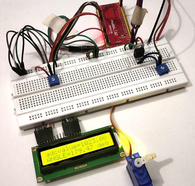
LCD_SEND(0x80);
sprintf(displayadc, "adcvalue=%f", dutycycle);
LCD_DISPLAY(displayadc);                                  //Display ADC value (0 to 1023)
angle =  (adcvalue/5.7);                       //Formula to convert ADC value into angle (o to 180 deg)
LCD_SEND(0xC0);
sprintf(anglevalue, "ANGLE=%.2f deg  ", angle);
LCD_DISPLAY(anglevalue);
Complete code and video description of the tutorial are given below
Complete Project Code
//INTERFACING SERVO MOTOR WITH ARM7-LPC2148
//CIRCUIT DIGEST
//Code by Pramoth.T

#include <lpc214x.h>
#include<stdint.h>
#include <stdio.h>
#include <string.h>

void initilizePLL(void);


void initilizePLL (void)      //Function to use PLL for clock generation
{
  PLL0CON = 0x01;
  PLL0CFG = 0x24;
  PLL0FEED = 0xAA;
  PLL0FEED = 0x55;
  while(!(PLL0STAT & 0x00000400));
  PLL0CON = 0x03;
  PLL0FEED = 0xAA;
  PLL0FEED = 0x55;
  VPBDIV = 0x01;
}

void delay_ms(uint16_t z)     // function to generate 1 milisecond delay with Cclk (60MHz)
{
    uint16_t x,i;
for(i=0;i<z;i++)
{
    for(x=0; x<6000; x++);
}
}

__irq void PWM_ISR (void)
{
if ( PWMIR & 0x0001 )
{
PWMIR = 0x0001;
}

if ( PWMIR & 0x0008 )
{
PWMIR = 0x0008;
}

VICVectAddr = 0x00000000;
}

void LCD_SEND(char command)                                  //Function to send hex commands
{
IO0PIN = ( (IO0PIN & 0xFFFF00FF) | ((command & 0xF0)<<8) );  //Send upper nibble of command
IO0SET = 0x00000040;                                         //Making Enable HIGH
IO0CLR = 0x00000030;                                         //Making RS & RW LOW
delay_ms(5);
IO0CLR = 0x00000040;                                         //Makeing Enable LOW
delay_ms(5);
IO0PIN = ( (IO0PIN & 0xFFFF00FF) | ((command & 0x0F)<<12) ); //Send Lower nibble of command
IO0SET = 0x00000040;                                         //ENABLE HIGH
IO0CLR = 0x00000030;                                         //RS & RW LOW
delay_ms(5);
IO0CLR = 0x00000040;                                         //ENABLE LOW
delay_ms(5);
}

void LCD_INITILIZE(void)                                     //Function to get ready the LCD
{
IO0DIR = 0x0000FFF0;                                         //Sets pin P0.12,P0.13,P0.14,P0.15,P0.4,P0.6 as OUTPUT
delay_ms(20);
LCD_SEND(0x02);                                              // Initialize lcd in 4-bit mode of operation
LCD_SEND(0x28);                                              // 2 lines (16X2)
LCD_SEND(0x0C);                                              // Display on cursor off
LCD_SEND(0x06);                                              // Auto increment cursor
LCD_SEND(0x01);                                              // Display clear
LCD_SEND(0x80);                                              // First line first position
}

void LCD_DISPLAY (char* msg)                                 //Function to print the characters sent one by one
{
uint8_t i=0;
while(msg[i]!=0)
{
IO0PIN = ( (IO0PIN & 0xFFFF00FF) | ((msg[i] & 0xF0)<<8) );   //Sends Upper nibble
IO0SET = 0x00000050;                                         //RS HIGH & ENABLE HIGH to print data
IO0CLR = 0x00000020;                                         //RW LOW Write mode
delay_ms(2);
IO0CLR = 0x00000040;                                         // EN = 0, RS and RW unchanged(i.e. RS = 1, RW = 0)
delay_ms(5);
IO0PIN = ( (IO0PIN & 0xFFFF00FF) | ((msg[i] & 0x0F)<<12) );  //Sends Lower nibble
IO0SET = 0x00000050;                                         //RS & EN HIGH
IO0CLR = 0x00000020;
delay_ms(2);
IO0CLR = 0x00000040;
delay_ms(5);
i++;
}
}


int main()
{
    LCD_INITILIZE();                               //Calls function to get ready the LCD to display
char displayadc[18];
float adc;
float angle;
char anglevalue[18];
        LCD_DISPLAY("CIRCUIT DIGEST");
delay_ms(900);
LCD_SEND(0xC0);
LCD_DISPLAY("SERVO LPC2148");
delay_ms(900);

PINSEL0 |= 0x00000008;                         // Setting pin P0.1 of LPC2148 as PWM3
VICVectAddr0 = (unsigned) PWM_ISR;             // PWM ISR Address
VICVectCntl0 = (0x00000020 | 8);               // Enable PWM IRQ slot
VICIntEnable = VICIntEnable | 0x00000100;      // Enable PWM interrupt
VICIntSelect = VICIntSelect | 0x00000000;      // PWM configured as IRQ
PWMTCR = 0x02;                                 // Reset and disable counter for PWM
PWMPR = 0x1D;                                  // Prescale Register value
PWMMR0 = 20000;                                // Time period of PWM wave, 20msec
PWMMR3 = 650;                                // Ton of PWM wave 0.65 msec
PWMMCR = 0x00000203;                        // Reset and interrupt on MR0 match, interrupt on MR3 match
PWMLER = 0x09;                                // Latch enable for PWM3 and PWM0
PWMPCR = 0x0800;                        // Enable PWM3 and PWM 0, single edge controlled PWM
PWMTCR = 0x09;                                // Enable PWM and counter

        float dutycycle;
        unsigned short int adcvalue;

        PINSEL1 = 0x01000000;                          //Setting P0.28 as ADC INPUT (from potentimeter)
        AD0CR = (((14)<<8) | (1<<21));                 //Setting clock and PDN for A/D Conversion
        PWMPCR |= (1<<9);                              //To enable PWM3 output at pin P0.1 of LPC2148 for servo (orange wire)

 while(1)
  {
        AD0CR |= (1<<1);                               //Select AD0.1 channel in ADC register
        AD0CR |= (1<<24);                              //Start the A/D conversion
        while( (AD0DR1 & (1<<31)) == 0 );              //Check the DONE bit in ADC Data register
        adcvalue = (AD0DR1>>6) & 0x3ff;                //Get the RESULT from ADC data register
        dutycycle = (adcvalue/4);                      //formula to get dutycycle values from (0 to 255)
        PWMMR3 = dutycycle;                            //set dutycycle value to PWM match register
        PWMLER = 0x08;                                 //Enable PWM output with dutycycle value
        delay_ms(50);
        LCD_SEND(0x80);
        sprintf(displayadc, "adcvalue=%f", dutycycle);
        LCD_DISPLAY(displayadc);        //Display ADC value (0 to 1023)
        angle =  (adcvalue/5.7);                       //Formula to convert ADC value into angle (o to 180 deg)
        LCD_SEND(0xC0);
        sprintf(anglevalue, "ANGLE=%.2f deg  ", angle);
        LCD_DISPLAY(anglevalue);                       //Display angle value
  }
}

Bonjour,
Le code ne fonctionne pas et pourtant le cablage est bon.
Bien à vous