
Every electronics engineer loves to break electronics things and explore what is present inside it. Recently I opened an LED TV and found ARM Chip inside it. ARM based microcontrollers are heavily used in various types of embedded products and systems. They comprise many advanced features that make them powerful and superior to other microcontrollers such as 8051, AVR and PIC. LPC2148 is one of the most commonly used ARM based Microcontroller, so we will create a series of LPC2148 tutorials and projects and share in upcoming articles. Here is the first tutorial in this series covering Getting started with LPC2148 and program it to blink LED.
So in this tutorial we will get to know about ARM7 Stick - LPC2148 and will learn how to program it with software Keil uVision and Flash magic. We will program our LPC2148 to blink an LED.
ARM Microcontroller
ARM (Advanced RISC Machines) originally known as Acorn RISC Machine is a family of reduced instruction set computing (RISC) architecture for computer processors, configured for various environments. Arm holdings is a British company who developed this architecture and licensed it to other companies, who design their own product by using this architecture.
ARM processor is widely found in electronics products such as LED TV, mobile phones, tablets, multimedia devices, gaming devices etc. Even popular electronics company like Apple’s mobiles and iPods, Raspberry pi 3 uses ARM architecture and Arm processor in it. Arm Architecture Examples: ARM7, ARM9, ARM11, CORTEX.
Benefits of ARM
- With more features ARM processor consumes less power.
- ARM processor are cheap and that’s why widely used in consumer electronics
- Performs one operation at a time and works faster.
Materials Required
Hardware
- ARM7 Stick – LPC2148
- LED
- Breadboard
- Jumper wires
Software
Introduction to ARM7 Stick - LPC2148 Board
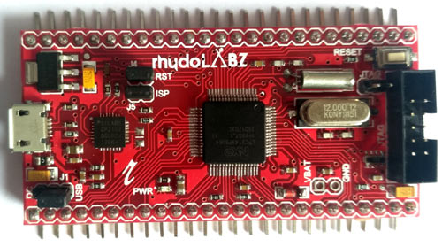
From the Rhydolabz Stick Series Quick Start boards this board contains NXP’s LPC-2148 microcontroller IC in it which belongs to ARM7 family. It is a high performance ARM7 TDMI-S based 32-bit RISC Microcontroller. This board is a good choice for beginners and also can be used in high end applications because of its inbuilt peripherals.
Features of ARM7 Stick
The ARM7 Stick comes with onboard LDO regulator for 3V3 Supply. They can be USB powered or externally powered by just changing the jumper. It has a on board USB to Serial converter and it also comes with boot loader code and USB interface for Serial communication and Programming. It has a Push button to hardware reset the controller. The board contains JTAG connector with 2x5 pin layout for programming/debugging and jumper pins to switch the USB interface between MCU USB pins and UART pins. It also has RTC battery backup pins and power Indication LED.
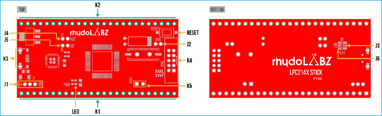
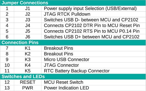
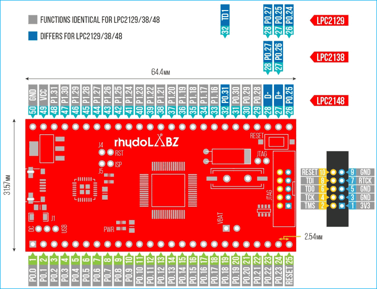
Image below shows the features present in ARM7 Stick
Specifications
- Architecture: 16-bit/32-bit ARM7TDMI-S
- CPU Frequency: 60 MHz
- Number of GPIO pins: 45 (5V-Tolarant)
- PWM Outputs: 6
- ADC: Two 14-Channel (10-bit)
- DAC: Single 10-bit DAC
- USART Peripherals: 2
- I2C Peripherals: 2 (40bits/s)
- SPI Peripherals: 1
- SSP Peripheral: 1
- Timers: 2(32-bit)
- Flash Memory: 512KB On-chip flash memory
- RAM: 40kB On-chip Static RAM
- Interrupt Pins: 21
- Input Voltage: 4.5V ~ 6.5V
- Current Draw: 500mA @5V
- Dimensions: 64.5 x 31.5 MM
If you want to know more about technical features go through the datasheet of LPC2148 stick from RhydoLABZ.
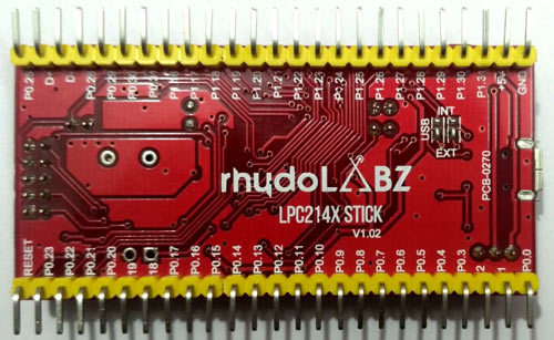
Pin Details of ARM7 Stick
The complete pin-outs of ARM7 Stick is shown below. The pin numbers are present at the backside of the board. The Ground pin is indicated as GND. The 5V pin is for DC input. Now let’s see about the I/O pins. LPC2148 has two IO ports (P0 & P1) each of them are 32-bit wide. We need to understand the labelling let’s say Pa.b where a is for port number and b for pin number from (0-31).Example P0.7 which indicates port 0 and pin 7.
IMPORTANT: Each pin can perform multiple functions like PWM or ADC or GPIO etc. So we need specify them while programming that where we use registers to configure them. Let’s see about registers later in this tutorials.
Pin Details
|
PORT |
PINS |
TYPE |
DESCRIPTION |
|
PORT 0
|
P0.0 to P0.31 |
INPUT/OUTPUT |
32-Bit I/O with individual bi-directional control 28 Pins for GPIO Pin P0.31 for Digital output function only Pins P0.24, P0.26, P0.27 are not available |
|
PORT1 |
P1.16 to P1.31 |
INPUT/OUTPUT |
32-Bit I/O with individual bi-directional control 16 Pins for GPIO Pins P1.0 to P1.15 are not available
|
Registers in ARM7 LPC-2148
Before we get into the programming we must know how to configure pins in LPC-2148.That where the registers come into action.
|
REGISTER NAME |
WHAT DOES IT DO |
|
IOPIN |
GPIO Port PIN Value Register Can be used to read the CURRENT STATE OF GPIO configured port pin |
|
IODIR |
GPIO Direction Control Register This individually controls direction of each port pin |
|
IOSET |
GPIO Output SET register Controls State of OUTPUT pins in conjunction with IOCLR Writing ONE: produces HIGH at corresponding port pins. Writing ZERO : No effects
|
|
IOCLR |
GPIO Output CLEAR register Controls State of OUTPUT pins Writing ONE : produces LOW at corresponding ports pins Clears corresponding bits in IOSET register Writing ZERO : No effects
|
The above table shows the registers that are used to configure the I/O ports.
Using These Registers as Individual Registers
1. IOSELX: Where X is 0,1,2. IOSEL is used to select functions. As each pin have multiple functions.
|
IOSELx |
SELECT FUNCTION OF PINS |
|
IOSEL0 |
P0.0 to P0.15 |
|
IOSEL1 |
P0.16 to P0.31 |
|
IOSEL2 |
P0.16 to P0.31 |
Each pin has 4 functions so 2-bits/pin is provided for selecting function On RESET all pins are configured as GPIO pins.
|
Value |
FUNCTION |
|
00 |
FUNCTION 0 (DEFAULT=GPIO) |
|
01 |
FUNCTION1 |
|
10 |
FUNCTION2 |
|
11 |
FUNCTION3 |
2. For using IODIR, IOSET, IOCLR for corresponding port and pin we need to specify them by following
IO_DIR, IO_SET, IO_CLR. We need to include just the port number we want to use.
Below table shows some examples for using registers and how we configure them.
|
REGISTER |
PORT |
SETTINGS |
EXAMPLE |
|
IO0DIR |
PORT 0 |
INPUT PIN : 0 OUTPUT PIN : 1 |
IO0DIR = (1<<10) P0.10 as OUTPUT |
|
IO1DIR |
PORT 1 |
INPUT PIN : 0 OUTPUT PIN : 1 |
IO1DIR= (1<<20) P1.20 as OUTPUT |
|
IO0SET |
PORT 0 |
SET : 1 |
IO0SET =(1<<10) P0.10 as HIGH |
|
IO0CLR |
PORT 0 |
CLEAR : 1 |
IO0CLR=(1<<10) P0.10 as LOW |
|
IO1SET |
PORT 1 |
SET : 1 |
IO1SET=(1<<20) P1.20 as HIGH |
|
IO1CLR |
PORT 1 |
CLEAR : 1 |
IO1CLR=(1<<20) P1.20 as LOW |
Programming ARM7 LPC2148 Stick
The LPC2148 Stick comes with pre-programmed boot loader, can be programmed using USB-UART interface available on-board. Also, the board can be powered using the same USB connector. It is also programmable via JTAG interface. But in this tutorial we are using USB connector.
For Programming we use KEIL uVISION which can create HEX file from C language and use FLASH MAGIC tool to dump HEX file into ARM7 Stick.
So let’s gets start with blinking LED program. So in this tutorial we will show you
- How to install KEIL uVISION 5 And install ARM7 IDE for KEIL
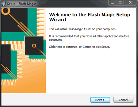
- How to install Flash Magic
- Then convert our Program .C to HEX file
- Then Flashing HEX file into ARM7 Stick
Installing KEIL uVISION 5 with ARM7 Packages & Flash Magic
Step 1: Download required files from the link below
Step 2: Install Keil uVision 5
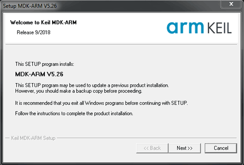
Step 3: Wait for installation it takes some minutes
Step 4: After successful installing of Keil uVision 5 we need to install KEIL LEGACY SUPPORT FOR
ARM7 as in KEIL uVISION 5 this package is not included.
Step 5: Open link given above and download packages.
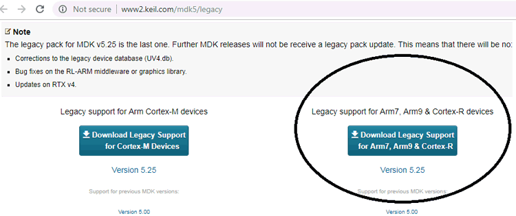
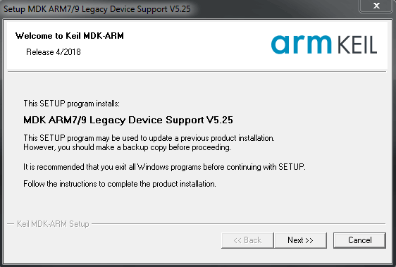
Step 6: Install the package. This will take few minutes.
Step 7: Now keil uVision is ready. Next download the Flash Magic Tool from the link given above in step1 and install it
Now we have installed all the softwares successfully, now we will make the hardware connections and see how to create a new project and make a hex file using Keil uVision and to flash hex file into ARM7 Stick using flash magic.
Circuit Connections

The Table below shows the circuit connections.
|
ARM7 Stick |
LED |
|
GND |
CATHODE |
|
P0.10 |
TO ANODE OF LED THROUGH RESISTOR |
Creating a New Project in Keil uVision 5 for ARM7 LPC2148
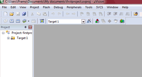
Step 1: Open Keil uVision

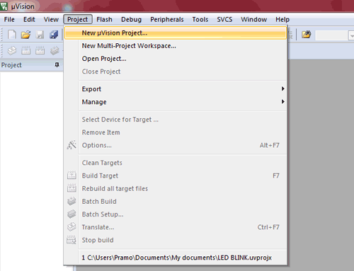
Step 2: Now open Project –> New uVision Project
Step 3: Give Name to Project e.g. “firstproject” and save it.
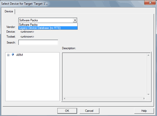
Step 4: We will get popup box Select Device for Target “Target1”. There will be a drop down menu where we have to select Legacy Device Database [no RTE].
NOTE: If you didn’t install ARM7 packages this Legacy device database wont appear here, so make sure you install those packages.
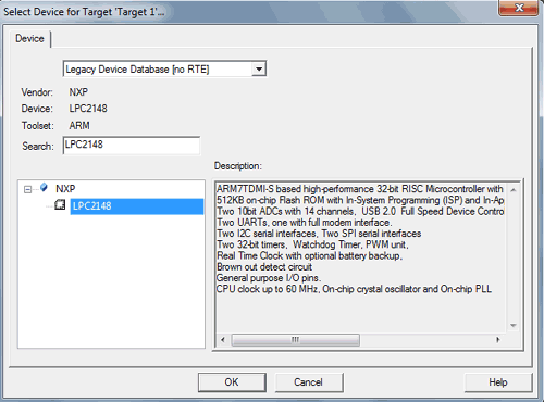
Step 5: Select our Device name LPC2148 and click OK
Step 6: A dialogue box appears to copy Startup.s to project folder, just click yes
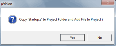
Step 7: Now it appears like the below image.
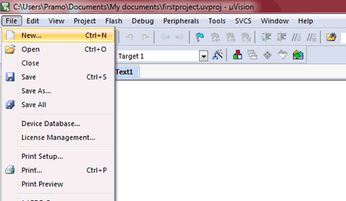
Step 8: Now Click File >> New
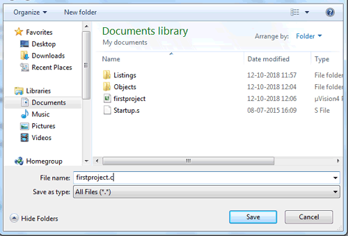
Step 9: Now do the programming’s here in text area. After doing coding click File >>Save As
Step 10: Now save as the file name with .C extension. We used firstproject.c
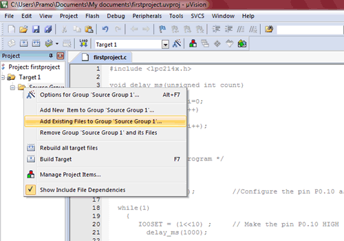
Step 11: Now Right click on Source Group 1 present left side and click Add Existing Files to Group ‘Source Group 1’
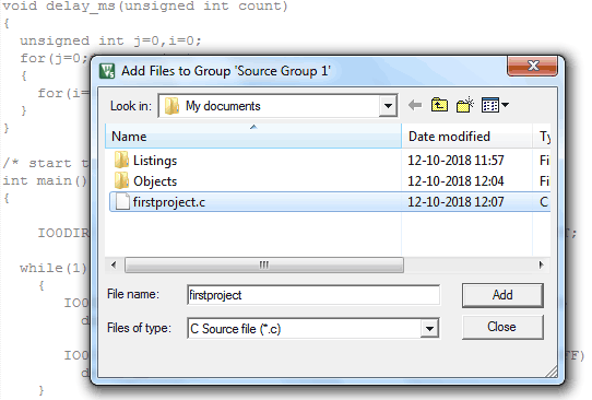
Step 12: Now Add files to Group ‘Source Group1’dialog box appears. Now select the file you saved with .C extension and then click add, then click close
Step 13: Now the firstproject.c file is included. See the image below.
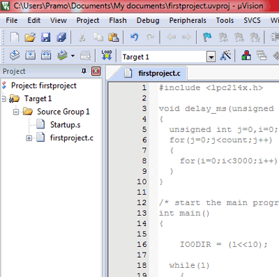
Step 14: Now click Options for target icon. You can see below image to fins where it is.
![]()
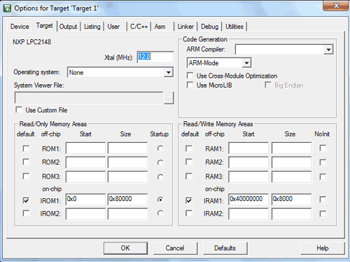
Step 15: Now in Options for Target ‘Target 1’ open tab Target give Xtal (Mhz) as 12
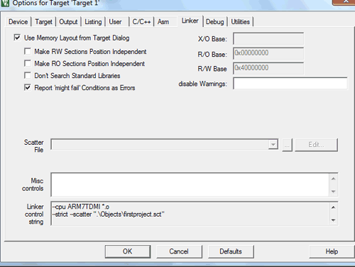
Step 16: In Linker tab, tick Use memory layout from Target dialog
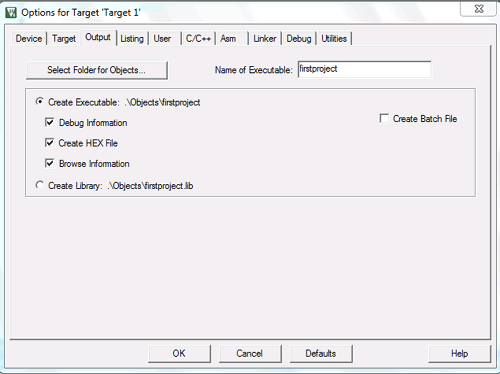
Step 17: Now under output tab tick create Hex file and then click ‘Ok’
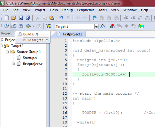
Step 18: Now click on BUILD icon or press F7 to create hex file.
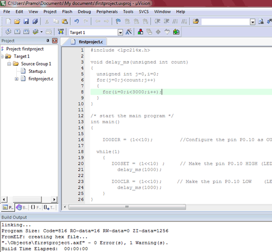
Step 19: Now the hex file is created and we can note it down at the bottom. As like this image below as it indicates hex file is created.
Step 20: Now it’s time to flash the hex file to ARM7 Stick. So open Flash Magic
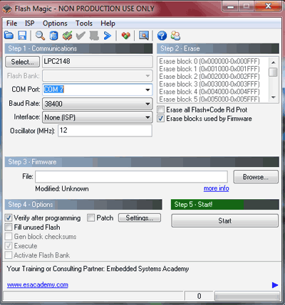
The Flash magic tool appears as above.
Below are the steps for flashing the the ARM LPC2148:
- Select the LPC2148
- Give the COM port number according to Device Manager (Mine was COM7)
- Give baud rate as 38400
- Oscillator as 12 Mhz
- Tick “Erase blocks used by firmware”
- Now select the hex file path
- Tick verify after programming checkbox.
- And click START
After successfully flashing in seconds, Finished (In green Colour) appears at the bottom as shown in image below
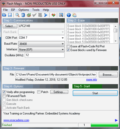
Now you can see the that LED starts blinking on the breadboard
Coding Explanation
Complete code for blinking LED with LPC2148 is given below. Code is simple and can be easily understood.
This header file includes all files for LPC214x series of microcontrollers.
#include <lpc214x.h>
As we have connected output to P0.10 it uses the IODIR register and make the pin Port 0 Pin 10 as output.
IO0DIR = (1<<10);
This register sets the P0.10 to HIGH making LED ON.
IO0SET = (1<<10) ;
This register clears the P0.10 to LOW making LED OFF
IO0CLR = (1<<10);
Below statements are present in while loop to execute the code continuously
  while(1)
    {
       IO0SET = (1<<10) ;
         delay_ms(1000);

       IO0CLR = (1<<10);
         delay_ms(1000);
    }
Functions delay_ms is used to create a delay time between SET & CLR to blink the LED in the interval of 1 second.
Complete code with a demonstration Video is given below.
Complete Project Code
#include <lpc214x.h>            //include header files for LPC-214x series
void delay_ms(unsigned int count)
{
  unsigned int j=0,i=0;
  for(j=0;j<count;j++)                                           //For loop to create delay
  {
    for(i=0;i<3000;i++);
  }
}

int main()
{
    IO0DIR = (1<<10);         //Configure the pin P0.10 as OUTPUT;
  while(1)                                    // While loop to execute program continueously
    {
       IO0SET = (1<<10) ;     // Make the pin P0.10 HIGH (LED ON)
         delay_ms(1000);
       IO0CLR = (1<<10);     // Make the pin P0.10 LOW    (LED OFF)
         delay_ms(1000);
    }
}
