
Display is the necessary part of a machine whether it is any home appliance or industrial machines. Display not only shows the control options to operate the machine but also shows the status and output of task performed by that machine. There are many types of displays used in electronics like 7-segment display, LCD display, TFT touch screen display, LED display etc. 16x2 LCD display is the most basic one and also used display in some small electronics equipment, we have done lot of projects using 16x2 LCD including the basic interfacing with other microcontrollers:
- LCD Interfacing with 8051 Microcontroller
- Interfacing LCD with ATmega32 Microcontroller
- LCD Interfacing with PIC Microcontroller
- Interfacing 16x2 LCD with Arduino
- 16x2 LCD Interfacing with Raspberry Pi using Python
In this tutorial, we will see how to interface a 16x2 LCD with ARM7-LPC2148 microcontroller and display a simple welcome message. If you are new with ARM7 then start with basics of ARM7 LPC2148 and learn how it can be programmed using Keil uVision
Materials Required
Hardware
- ARM7-LPC2148 Microcontroller board
- LCD (16X2)
- Potentiometer
- 5V voltage regulator IC
- Breadboard
- Connecting Wires
- 9V battery
- Micro USB cable
Software
- Keil uVision 5
- Magic Flash Tool
Before getting into the project we must know few things about the LCD modes of operation and about the LCD Hex codes.
16X2 LCD Display Module
A 16X2 LCD says that it has 16 Columns and 2 Rows. This LCD has 16 pins. Below image and table shows the pin names of LCD display and its functions.
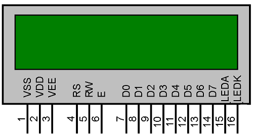
NAME | FUNCTION |
VSS | Ground Pin |
VDD | +5V Input Pin |
VEE | Contrast Adjust Pin |
RS | Register Select |
R/W | Read/Write Pin |
E | Enable Pin |
D0-D7 | Data Pins (8 Pins) |
LED A | Anode Pin (+5V) |
LED K | Cathode Pin (GND) |
The LCD can work in two different modes, namely the 4-bit mode and the 8-bit mode. In 4 bit mode we send the data nibble by nibble, first upper nibble and then lower nibble. For those of you who don’t know what a nibble is: a nibble is a group of four bits, so the lower four bits (D0-D3) of a byte form the lower nibble while the upper four bits (D4-D7) of a byte form the higher nibble. This enables us to send 8 bit data.
Whereas in 8 bit mode we can send the 8-bit data directly in one stroke since we use all the 8 data lines.
Here in this project we will use the most commonly used mode which is 4-bit mode. In four bit mode we can save 4 pins of microcontroller and also reduce the wiring overhead.
16x2 also uses HEX code to take any command, there are many hex commands for LCD like to move the cursor, select the mode, shift the control to second line etc. To know more about 16X2 LCD Display Module and hex commands, follow the link.
Circuit Diagram and Connections

Below table shows the circuit connections between LCD & ARM7-LPC2148.
ARM7-LPC2148 | LCD (16x2) |
P0.4 | RS (Register Select) |
P0.6 | E (Enable) |
P0.12 | D4 (Data pin 4) |
P0.13 | D5(Data pin 5) |
P0.14 | D6(Data pin 6) |
P0.15 | D7 (Data pin 7) |
Connections of Voltage Regulator with LCD & ARM7 Stick
Below table shows the connections between ARM7 & LCD with voltage regulator.
Voltage Regulator IC | Pin function | LCD & ARM-7 LPC2148 |
1.Left Pin | + Ve from battery 9V Input | NC |
2.Centre Pin | - Ve from battery | VSS,R/W,K of LCD GND of ARM7 |
3.Right Pin | Regulated +5V Output | VDD,A of LCD +5V of ARM7 |
Potentiometer with LCD
A potentiometer is used to vary the contrast of LCD display. A pot has three pins, Left pin (1) is connected to +5V and centre (2) to VEE or V0 of LCD module and right pin (3) is connected to GND. We can adjust the contrast by turning the knob.
Jumper Settings
A jumper pin is present in ARM7-Stick so that we can power & upload code by using USB or by using a 5V DC input for power only. You can see the below images.
Below image shows that the jumper is in DC position. That means we must power the board from external 5V supply.

And this image shows that jumper is connected in USB mode. Here the power and code is provided via micro usb port.

NOTE: Here in this tutorial we have uploaded code by using USB by setting jumper to USB and then changed jumper to DC mode to power LPC2148 from 5v input of regulator. You can check out this in the video given at the end.
The final circuit for interfacing 16x2 LCD with ARM7 Microcontroller will look like this:

Programming ARM7-LPC2148
To Program ARM7-LPC2148 we need keil uVision & Flash Magic tool. We are using USB Cable to program ARM7 Stick via micro USB port. We write code using Keil and create a hex file and then the HEX file is flashed to ARM7 stick using Flash Magic. To know more about installing keil uVision and Flash Magic and how to use them follow the link Getting Started With ARM7 LPC2148 Microcontroller and Program it using Keil uVision.
The complete code for interfacing LCD with ARM 7 is given at the end of this tutorial, here we are explaining few parts of it.
First of all we need to include the required header files
#include <lpc214x.h> -Header File to include LPC214x libraries
#include <stdint.h> -Header File for using integer type with specified widths
#include <stdlib.h>  - Header File for include standard library
#include <stdio.h>  -   Header File for include standard input output library
Initializing the LCD module is a very important step. Here we use certain HEX codes, that are actually commands, to tell the LCD about the mode of operation (4-bit) , type of LCD (16x2), start line etc.
void LCD_INITILIZE(void)          //Function to get ready the LCD
{
    IO0DIR = 0x0000FFF0;  //Sets pin P0.4,P0.6 ,P0.12,P0.13,P0.14,P0.15as OUTPUT
     delay_ms(20);

LCD_SEND(0x02);  // Initialize lcd in 4-bit mode of operation
LCD_SEND(0x28);  // 2 lines (16X2)
LCD_SEND(0x0C);   // Display on cursor off
LCD_SEND(0x06);  // Auto increment cursor
LCD_SEND(0x01);   // Display clear
LCD_SEND(0x80);  // First line first position
}
For 4-Bit mode we have different type of write function for the pins, that is by using upper & lower nibble. Let’s see, how it is done
void LCD_SEND(char command)     //Function to send hex commands nibble by nibble
{
IO0PIN = ( (IO0PIN & 0xFFFF00FF) | ((command & 0xF0)<<8) ); //Send upper nibble of command
IO0SET = 0x00000040; //Making Enable HIGH
IO0CLR = 0x00000030; //Making RS & RW LOW
delay_ms(5);
IO0CLR = 0x00000040; //Makeing Enable LOW
delay_ms(5);
IO0PIN = ( (IO0PIN & 0xFFFF00FF) | ((command & 0x0F)<<12) ); //Send Lower nibble of command
IO0SET = 0x00000040;  //ENABLE HIGH
IO0CLR = 0x00000030;  //RS & RW LOW
delay_ms(5);
IO0CLR = 0x00000040;  //ENABLE LOW
delay_ms(5);
}
Nibble Sending Logic
IO0PIN = ( (IO0PIN & 0xFFFF00FF) | ((command & 0x0F)<<12) ); //Send Lower nibble of command
IO0PIN = ( (IO0PIN & 0xFFFF00FF) | ((command & 0xF0)<<8) ); //Send upper nibble of command
Above two statements play an important role in this program. First command sends lower nibble & second sends the upper nibble. That is without affecting the other pins we do. Let’s see how it is happening before that get to know about this logic first
ORing- (A|0=A),(A|1=1)
ANDing-(A&0=0),(A&1=A)
So we use a masking concept and logical shift operation without affecting the other pins. Means only the pins (P0.12-P0.15) are used and no other pins such as P0.4, P0.6 are affected. It will be done by shifting the data in four bits and making the upper nibble in the place of lower nibble and masking the upper nibble. And then we make the lower bits zero (0XF0) and ORed with the nibble data to get the upper nibble data at the output.
Similar process is used for lower nibble data but here we need not to shift the data.
While writing data to output, that is, in command mode RS should be LOW and to execute enable must be HIGH, and in data mode RS should be HIGH and to execute enable must be HIGH.
Now for sending the string data that is to be printed at the output, same principle is used nibble by nibble. Important step here is REGISTER SELECT (RS) must be HIGH for data mode.
void LCD_DISPLAY (char* msg) //Function to print the characters sent one by one
{
uint8_t i=0;
while(msg[i]!=0)
{
IO0PIN = ( (IO0PIN & 0xFFFF00FF) | ((msg[i] & 0xF0)<<8) ); //Sends Upper nibble
IO0SET = 0x00000050; //RS HIGH & ENABLE HIGH to print data
IO0CLR = 0x00000020; //RW LOW Write mode
delay ms(2);
IO0CLR = 0x00000040; // EN = 0, RS and RW unchanged(i.e. RS = 1, RW = 0)
delay ms(5);
IO0PIN = ( (IO0PIN & 0xFFFF00FF) | ((msg[i] & 0x0F)<<12) ); //Sends Lower nibble
IO0SET = 0x00000050; //RS & EN HIGH
IO0CLR = 0x00000020;
delay ms(2);
IO0CLR = 0x00000040;
delay ms(5);
i++;
}
Complete Coding & Demonstration video is given below.
Complete Project Code
//Interfacing LCD with ARM7-LPC2148 (4-Bit Mode)
//CIRCUIT DIGEST
//Pramoth.T
#include <lpc214x.h>       //Header File to include LPC214x libraries
#include <stdint.h>        //Header File for using integer type with specified widths
#include <stdlib.h>        //Header File for include standard library
#include <stdio.h>         //Header File for include standard input output library

void delay_ms(uint16_t j)  // Function for making delay in milliseconds
{
    uint16_t x,i;
for(i=0;i<j;i++)
{
    for(x=0; x<6000; x++);    // Forloop to generate 1 millisecond delay with Cclk = 60MHz
}
}

void LCD_SEND(char command)     //Function to send hex commands
{
IO0PIN = ( (IO0PIN & 0xFFFF00FF) | ((command & 0xF0)<<8) ); //Send upper nibble of command
IO0SET = 0x00000040; //Making Enable HIGH
IO0CLR = 0x00000030; //Making RS & RW LOW
delay_ms(5);
IO0CLR = 0x00000040; //Makeing Enable LOW
delay_ms(5);
IO0PIN = ( (IO0PIN & 0xFFFF00FF) | ((command & 0x0F)<<12) ); //Send Lower nibble of command
IO0SET = 0x00000040;  //ENABLE HIGH
IO0CLR = 0x00000030;  //RS & RW LOW
delay_ms(5);
IO0CLR = 0x00000040;  //ENABLE LOW
delay_ms(5);
}

void LCD_INITILIZE(void)          //Function to get ready the LCD
{
IO0DIR = 0x0000FFF0; //Sets pin P0.12,P0.13,P0.14,P0.15,P0.4,P0.6 as OUTPUT
delay_ms(20);
LCD_SEND(0x02);  // Initialize lcd in 4-bit mode of operation
LCD_SEND(0x28);  // 2 lines (16X2)
LCD_SEND(0x0C);   // Display on cursor off
LCD_SEND(0x06);  // Auto increment cursor
LCD_SEND(0x01);   // Display clear
LCD_SEND(0x80);  // First line first position
}

void LCD_DISPLAY (char* msg)         //Function to print the characters sent one by one
{
uint8_t i=0;
while(msg[i]!=0)
{
IO0PIN = ( (IO0PIN & 0xFFFF00FF) | ((msg[i] & 0xF0)<<8) ); //Sends Upper nibble
IO0SET = 0x00000050;  //RS HIGH & ENABLE HIGH to print data
IO0CLR = 0x00000020;  //RW LOW Write mode
delay_ms(2);
IO0CLR = 0x00000040; // EN = 0, RS and RW unchanged(i.e. RS = 1, RW = 0)
delay_ms(5);
IO0PIN = ( (IO0PIN & 0xFFFF00FF) | ((msg[i] & 0x0F)<<12) ); //Sends Lower nibble
IO0SET = 0x00000050; //RS & EN HIGH
IO0CLR = 0x00000020;
delay_ms(2);
IO0CLR = 0x00000040;
delay_ms(5);
i++;
}
}

int main(void)
{
LCD_INITILIZE();                  //Function call INITILIZE
LCD_DISPLAY("CIRCUIT DIGEST");    //Function call DISPLAY with String arguments (put your message here)
LCD_SEND(0xC0);                   //Function call SEND with Hex command as argument
delay_ms(100);                    //Function call delay with delay time as argument
LCD_DISPLAY("LCD WITH LPC2148");  //Function call DISPLAY with our message (Puts your message here)
LCD_SEND(0xCC);                   //Function call SEND with Hex command as argument
return 0;
}
