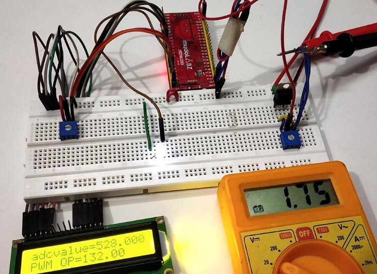
As we know microcontrollers take analog input from analog sensors and use ADC (Analog to Digital converter) to process those signals. But what if a microcontroller want to produce an analog signal to control analog operated devices like a Servo motor, DC motor etc? Microcontrollers don’t produce output voltage like 1V, 5V instead they use a technique called PWM for operating analog devices. An example of PWM is our laptop’s cooling fan (DC motor) which needs to be speed controlled according to the temperature, and the same is implemented by using Pulse Width Modulation (PWM) technique in motherboards.
In this tutorial we will control the brightness of a LED using the PWM in ARM7-LPC2148 microcontroller.
PWM (Pulse Width Modulation)
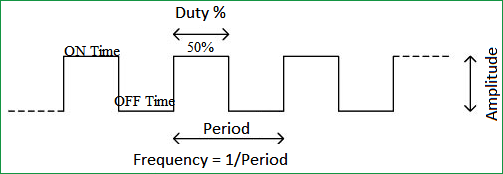
PWM is a good way to control the analog devices using digital value like controlling motor’s speed, brightness of a led etc. Although PWM doesn’t provide pure analog output, but it generates decent analog pulses to control the Analog Devices. PWM actually modulates the width of a rectangular pulse wave in order to get a variation in the average value of the resulting wave.
Duty cycle of the PWM
The percentage of time in which the PWM signal remains HIGH (on time) is called as duty cycle. If the signal is always ON it is in 100% duty cycle and if it is always off it is 0% duty cycle.
Duty Cycle =Turn ON time/ (Turn ON time + Turn OFF time)

Here are few PWM examples with other Microcontroller:
- Generating PWM using PIC Microcontroller with MPLAB and XC8
- Servo Motor Control with Raspberry Pi
- Arduino Based LED Dimmer using PWM
- Pulse width Modulation (PWM) using MSP430G2
Check all the PWM related projects here.
PWM in ARM7-LPC2148
ARM7-LPC2148 has 6 PWM pins and 14 ADC pins. It has 8-bit PWM resolution (28), that is counters and variables can be as large as 255, so:
- A digital value of 255 gives full brightness OF LED with (100% Duty Cycle)
- Likewise digital value of 127 gives 50% LED brightness with (50% Duty Cycle)
- And digital value of 64 gives 25% LED brightness with (25% Duty Cycle)

PWM Pins in ARM7-LPC2148
The image below indicates the PWM output pins of ARM7-LPC2148.There are total six pins for PWM.

|
PWM Channel |
LPC2148 Port Pins |
|
PWM1 |
P0.0 |
|
PWM2 |
P0.7 |
|
PWM3 |
P0.1 |
|
PWM4 |
P0.8 |
|
PWM5 |
P0.21 |
|
PWM6 |
P0.9 |
PWM Registers in ARM7-LPC2148
Before getting into our project we need to know about the PWM registers in LPC2148.
Here is the list of registers used in LPC2148 for PWM
1. PWMPR: PWM Prescale Register
Use: It’s a 32-Bit register. It contains the number of times (minus 1) PCLK must cycle before incrementing the PWM Timer Counter (It actually holds maximum value of prescale counter).
2. PWMPC: PWM Prescaler Counter
Use: It a 32-bit register. It contains the incrementing counter value. When this value equals the PR value plus 1, the PWM Timer Counter (TC) is incremented.
3. PWMTCR: PWM Timer Control Register
Use: It contains the Counter Enable, Counter Reset and the PWM Enable control bits. It is an 8-Bit register.
|
7:4 |
3 |
2 |
1 |
0 |
|
RESERVED |
PWM ENABLE |
RESERVED |
COUNTER RESET |
COUNTER ENABLE |
- PWM Enable: (Bit-3)
0- PWM Disabled
1- PWM Enabled - Counter Enable: (Bit-0)
0- Disable Counters
1- Enable Counter - Counter reset: (Bit-1)
0- Do Nothing.
1- Resets PWMTC & PWMPC on positive edge of PCLK.
4. PWMTC: PWM Timer Counter
Use: It’s a 32-Bit register. It contains the current value of the incrementing PWM Timer. When the Prescaler Counter (PC) reaches the Prescaler Register (PR) value plus 1, this counter is incremented.
5. PWMIR: PWM Interrupt Register
Use: It’s a 16-Bit Register. It contains the interrupt flags for PWM Match Channels 0-6. An interrupt flag is set when an interrupt occurs for that channel (MRx Interrupt) where X is the channel number (0 to 6).
6. PWMMR0-PWMMR6: PWM Match Register
Use: It’s a 32-Bit register. Actually the Match Channel group allows setting 6 single-edge controlled or 3 double-edge controlled PWM outputs. You may modify the seven Match Channels to configure these PWM outputs to suit your requirements in PWMPCR.
7. PWMMCR: PWM Match Control Register
Use: It’s a 32-Bit register. It contains the Interrupt, Reset and Stop bits that control the selected Match Channel. A match occurs between the PWM match registers and PWM Timer counters.
|
31:21 |
20 |
19 |
18 |
.. |
5 |
4 |
3 |
2 |
1 |
0 |
|
RESERVED |
PWMMR6S |
PWMMR6R |
PWMMR6I |
.. |
PWMMR1S |
PWMMR1R |
PWMMR11 |
PWMMR0S |
PWMMR0R |
PWMMR01 |
Here x is from 0 to 6
- PWMMRxI (Bit-0)
ENABLE OR DISABLE PWM interrupts
0- Disable PWM Match interrupts.
1- Enable PWM Match interrupt.
- PWMMRxR :(Bit-1)
RESET PWMTC -Timer counter value whenever it matches PWMRx
0- Do Nothing.
1- Resets the PWMTC.
- PWMMRxS :(Bit 2)
STOP PWMTC & PWMPC when PWMTC reaches the Match register value
0- Disable the PWM stop feature.
1- Enable the PWM Stop feature.
8. PWMPCR: PWM Control Register
Use: It’s a 16-Bit register. It contains the bits that enable PWM outputs 0-6 and select single-edge or double-edge control for each output.
|
31:15 |
14:9 |
8:7 |
6:2 |
1:0 |
|
UNUSED |
PWMENA6-PWMENA1 |
UNUSED |
PWMSEL6-PWMSEL2 |
UNUSED |
- PWMSELx (x: 2 to 6)
- Single Edge mode for PWMx
- 1- Double Edge Mode for PWMx.
- PWMENAx (x:1 to 6)
- PWMx Disable.
- 1- PWMx Enabled.
9. PWMLER: PWM Latch Enable Register
Use: It’s an 8-Bit Register. It contains the Match x Latch bits for each Match Channel.
|
31:7 |
6 |
5 |
4 |
3 |
2 |
1 |
0 |
|
UNUSED |
LEN6 |
LEN5 |
LEN4 |
LEN3 |
LEN2 |
LEN1 |
LEN0 |
LENx (x:0 to 6):
0- Disable the loading of new Match Values
1- Load the new Match values from (PWMMRx) PWMMatch Register when the timer is reset.
Now lets start building the hardware setup to demonstrate the Pulse Width Modulation in ARM microcontroller.
Components Required
Hardware
- ARM7-LPC2148 Microcontroller
- 3.3V Voltage Regulator IC
- 10k Potentiometer
- LED (Any colour)
- LCD (16x2) Display Module
- Breadboard
- Connecting Wires
Software
- Keil uVision5
- Flash Magic Tool
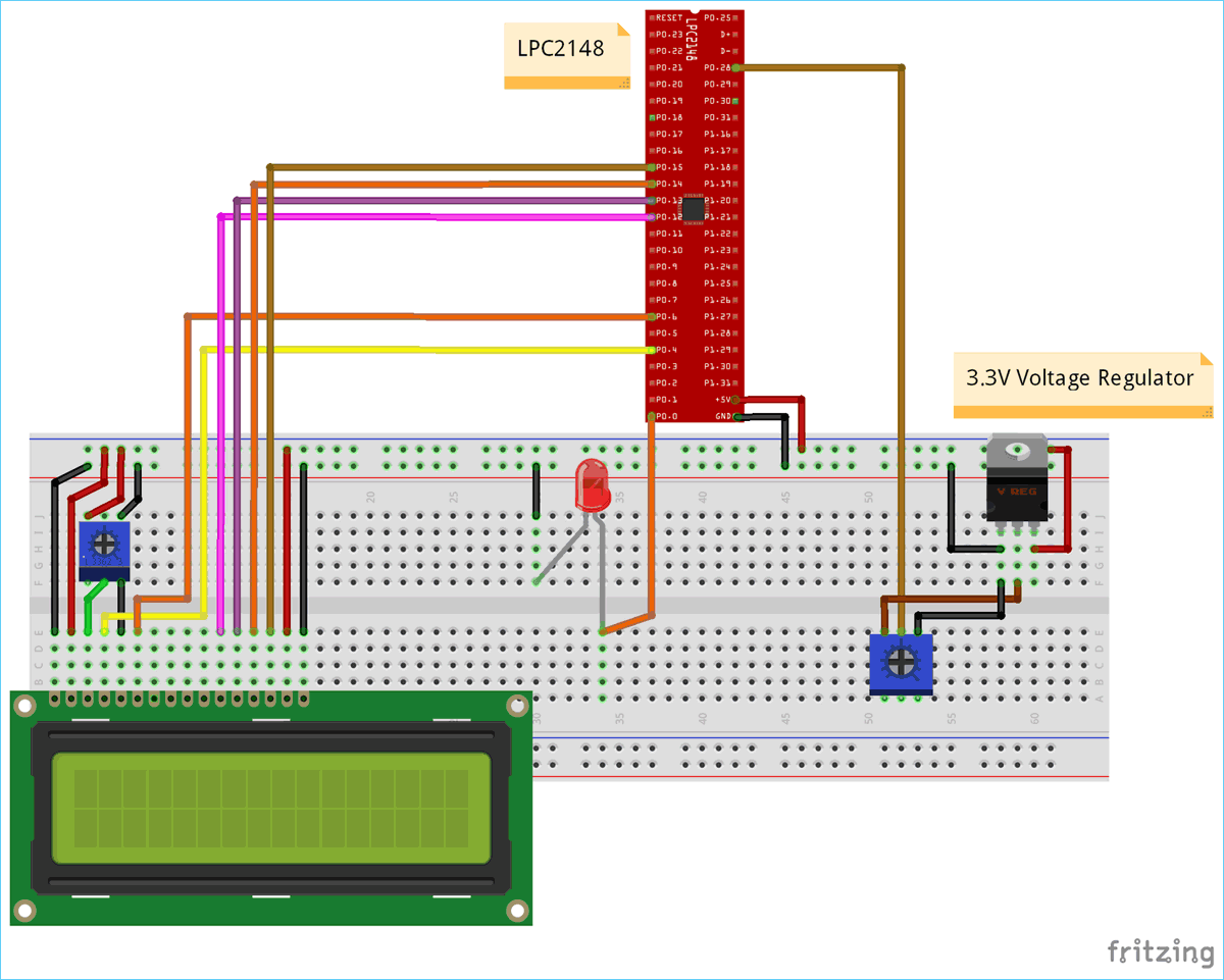
Circuit Diagram and Connections

Connections between LCD & ARM7-LPC2148
|
ARM7-LPC2148 |
LCD (16x2) |
|
P0.4 |
RS (Register Select) |
|
P0.6 |
E (Enable) |
|
P0.12 |
D4 (Data pin 4) |
|
P0.13 |
D5(Data pin 5) |
|
P0.14 |
D6(Data pin 6) |
|
P0.15 |
D7 (Data pin 7) |
|
GND |
VSS, R/W,K |
|
+5V |
VDD,A |
Connection between LED & ARM7-LPC2148
LED’s ANODE is connected to the PWM output (P0.0) of LPC2148, while LED’s CATHODE pin is connected to GND pin of LPC2148.
Connection between ARM7-LPC2148 and potentiometer with 3.3V voltage regulator
|
3.3V Voltage Regulator IC |
Pin function |
ARM-7 LPC2148 Pin |
|
1.Left Pin |
- Ve from GND
|
GND pin |
|
2.Centre Pin |
Regulated +3.3V Output
|
To potentiometer Input and potentiometer’s output to P0.28 of LPC2148 |
|
3.Right Pin |
+ Ve from 5V INPUT |
+5V |
Points to be noted
1. A voltage regulator of 3.3V is used here to provide analog input value to the ADC pin (P0.28) of LPC2148 and because we are using 5V power we need to regulate voltage with voltage regulator of 3.3V.
2. A Potentiometer is used to vary voltage between (0V to 3.3V) to provide analog input (ADC) to LPC2148 pin P0.28
Programming ARM7-LPC2148 for PWM
To Program ARM7-LPC2148 we need keil uVision & Flash Magic tool. We are using USB Cable to program ARM7 Stick via micro USB port. We write code using Keil and create a hex file and then the HEX file is flashed to ARM7 stick using Flash Magic. To know more about installing keil uVision and Flash Magic and how to use them follow the link Getting Started With ARM7 LPC2148 Microcontroller and Program it using Keil uVision.
In this tutorial we will use ADC and PWM technique to control the brightness of the LED. Here LPC2148 is given analog input (0 to 3.3V) via ADC input pin P0.28, then this analog input is converted into digital value (0 to 1023). Then this value is again converted into digital value (0 - 255) as PWM output of LPC2148 has only 8-bit resolution (28). LED is connected to PWM pin P0.0 and the brightness of the LED can be controlled using the potentiometer. To know more about ADC in ARM7-LPC2148 follow the link.
Steps involved in programming LPC2148 for PWM & ADC
Step 1:- The very first thing is to configure the PLL for clock generation as it sets the system clock and peripheral clock of LPC2148 as per programmers need. The maximum clock frequency for LPC2148 is 60Mhz. Following lines are used to configure PLL clock generation.
void initilizePLL (void)     //Function to use PLL for clock generation
{
  PLL0CON = 0x01;
  PLL0CFG = 0x24;
  PLL0FEED = 0xAA;
  PLL0FEED = 0x55;
  while(!(PLL0STAT & 0x00000400));
  PLL0CON = 0x03;
  PLL0FEED = 0xAA;
  PLL0FEED = 0x55;
  VPBDIV = 0x01;
}
Step 2:- Next thing is to select the PWM pins and PWM function of LPC2148 by using PINSEL register. We use PINSEL0 as we use P0.0 for PWM output of LPC2148.
PINSEL0 = 0x00000002; //Setting pin P0.0 for PWM output
Step 3:- Next we need to RESET the timers using PWMTCR (Timer Control Register).
PWMTCR = (1<<1); //Setting PWM Timer Control Register as counter reset
And then, set the prescale value which decides the resolution of PWM. I’m setting it to zero
PWMPR = 0X00; //Setting PWM prescale value
Step 4:- Next we need to set the PWMMCR (PWM match control register) as it sets operation like reset, interrupts for PWMMR0.
PWMMCR = (1<<0)|(1<<1); //Setting PWM Match Control Register
Step 5:- The maximum period of the PWM channel is set using PWMMR.
PWMMR0 = PWMvalue; //Giving PWM value Maximum value
In our case the maximum value is 255 (For maximum brightness)
Step 6:- Next we need to set the Latch Enable to the corresponding match registers using PWMLER
PWMLER = (1<<0); //Enalbe PWM latch
(We use PWMMR0) So enable the corresponding bit by setting 1 in PWMLER
Step 7:- To enable the PWM output to the pin we need to use the PWMTCR for enabling the PWM Timer counters and PWM modes.
PWMTCR = (1<<0) | (1<<3); //Enabling PWM and PWM counter
Step 8:- Now we need to get the potentiometer values for setting duty cycle of PWM from ADC pin P0.28. So we use ADC module in LPC2148 for converting potentiometers analog input (0 to 3.3V) to the ADC values (0 to 1023).
Here we are converting the values from 0-1023 to 0-255 by dividing it with 4 as PWM of LPC2148 has 8-Bit resolution (28).
Step 9:- For selecting ADC pin P0.28 in LPC2148, we use
PINSEL1 = 0x01000000;           //Setting P0.28 as ADC INPUT
AD0CR = (((14)<<8) | (1<<21)); //Setting clock and PDN for A/D Conversion
The following lines capture the Analog input (0 to 3.3V) and convert it into digital value (0 to 1023). And then this digital values are divided by 4 to convert them into (0 to 255) and finally fed as PWM output in P0.0 pin of LPC2148 on which the LED is connected.
AD0CR |= (1<<1);                   //Select AD0.1 channel in ADC register
delaytime(10);
AD0CR |= (1<<24);                  //Start the A/D conversion
while( (AD0DR1 & (1<<31)) == 0 );  //Check the DONE bit in ADC Data register
adcvalue = (AD0DR1>>6) & 0x3ff;     //Get the RESULT from ADC data register
dutycycle = adcvalue/4;             //formula to get dutycycle values from (0 to 255)
PWMMR1 = dutycycle;                 //set dutycycle value to PWM match register
PWMLER |= (1<<1);                        //Enable PWM output with dutycycle value
Step 10:- Next we display those values in the LCD (16X2) Display module. So we add the following lines to initializes LCD display module
Void LCD_INITILIZE(void)          //Function to get ready the LCD
{
IO0DIR = 0x0000FFF0; //Sets pin P0.12,P0.13,P0.14,P0.15,P0.4,P0.6 as OUTPUT
delaytime(20);

LCD_SEND(0x02);  // Initialize lcd in 4-bit mode of operation
LCD_SEND(0x28);  // 2 lines (16X2)
LCD_SEND(0x0C);   // Display on cursor off
LCD_SEND(0x06);  // Auto increment cursor
LCD_SEND(0x01);   // Display clear
LCD_SEND(0x80);  // First line first position
}
As we connected LCD in 4-Bit mode with LPC2148 we need to send values to be displayed as nibble by nibble (Upper Nibble & Lower Nibble). So following lines are used.
void LCD_DISPLAY (char* msg)         //Function to print the characters sent one by one
{
uint8_t i=0;
while(msg[i]!=0)
{
IO0PIN = ( (IO0PIN & 0xFFFF00FF) | ((msg[i] & 0xF0)<<8) ); //Sends Upper nibble
IO0SET = 0x00000050;  //RS HIGH & ENABLE HIGH to print data
IO0CLR = 0x00000020;  //RW LOW Write mode
delaytime(2);

IO0CLR = 0x00000040; // EN = 0, RS and RW unchanged(i.e. RS = 1, RW = 0)
delaytime(5);

IO0PIN = ( (IO0PIN & 0xFFFF00FF) | ((msg[i] & 0x0F)<<12) ); //Sends Lower nibble
IO0SET = 0x00000050; //RS & EN HIGH
IO0CLR = 0x00000020;
delaytime(2);

IO0CLR = 0x00000040;
delaytime(5);

i++;
}
}
To display those ADC & PWM values we use following lines in the int main() function.
LCD_SEND(0x80);
sprintf(displayadc, "adcvalue=%f", adcvalue);
LCD_DISPLAY(displayadc);     //Display ADC value (0 to 1023)
LCD_SEND(0xC0);
sprintf(ledoutput, "PWM OP=%.2f   ", brightness);
LCD_DISPLAY(ledoutput);    //Display dutycycle values from (0 to 255)

Complete code and video description of the tutorial are given below.
Complete Project Code
//PWM using ARM7-LPC2148 (Controlling the brightness of LED)
//CIRCUIT DIGEST
//Pramoth.T

#include <lpc214x.h>
#include <stdint.h>
#include <string.h>

void initilizePLL(void);
void initilizePWM(unsigned int periodPWM);
void delaytime(uint16_t j);

void initilizePLL (void)     //Function to use PLL for clock generation
{
  PLL0CON = 0x01;
  PLL0CFG = 0x24;
  PLL0FEED = 0xAA;
  PLL0FEED = 0x55;
  while(!(PLL0STAT & 0x00000400));
  PLL0CON = 0x03;
  PLL0FEED = 0xAA;
  PLL0FEED = 0x55;
  VPBDIV = 0x01;
}

void delaytime(uint16_t j)      // fucntion to generate 1 milisecond delay
{
    uint16_t x,i;
for(i=0;i<j;i++)
{
    for(x=0; x<6000; x++);
}
}

void initilizePWM(unsigned int PWMvalue)
{
  PINSEL0 = 0x00000002;         //Setting pin P0.0 for PWM output
  PWMTCR = (1<<1);              //Setting PWM Timer Control Register as counter reset
  PWMPR = 0X00;                 //Setting PWM prescale value
  PWMMCR = (1<<0)|(1<<1);       //Setting PWM Match Control Register
  PWMMR0 = PWMvalue;            //Giving PWM value Maximum value
  PWMLER = (1<<0);              //Enalbe PWM latch
  PWMTCR = (1<<0) | (1<<3);      //Enabling PWM and PWM counter
}

void LCD_SEND(char command)     //Function to send hex commands
{
IO0PIN = ( (IO0PIN & 0xFFFF00FF) | ((command & 0xF0)<<8) ); //Send upper nibble of command
IO0SET = 0x00000040; //Making Enable HIGH
IO0CLR = 0x00000030; //Making RS & RW LOW
delaytime(5);
IO0CLR = 0x00000040; //Makeing Enable LOW
delaytime(5);
IO0PIN = ( (IO0PIN & 0xFFFF00FF) | ((command & 0x0F)<<12) ); //Send Lower nibble of command
IO0SET = 0x00000040;  //ENABLE HIGH
IO0CLR = 0x00000030;  //RS & RW LOW
delaytime(5);
IO0CLR = 0x00000040;  //ENABLE LOW
delaytime(5);
}

void LCD_INITILIZE(void)          //Function to get ready the LCD
{
IO0DIR = 0x0000FFF0; //Sets pin P0.12,P0.13,P0.14,P0.15,P0.4,P0.6 as OUTPUT
delaytime(20);
LCD_SEND(0x02);  // Initialize lcd in 4-bit mode of operation
LCD_SEND(0x28);  // 2 lines (16X2)
LCD_SEND(0x0C);   // Display on cursor off
LCD_SEND(0x06);  // Auto increment cursor
LCD_SEND(0x01);   // Display clear
LCD_SEND(0x80);  // First line first position
}

void LCD_DISPLAY (char* msg)         //Function to print the characters sent one by one
{
uint8_t i=0;
while(msg[i]!=0)
{
IO0PIN = ( (IO0PIN & 0xFFFF00FF) | ((msg[i] & 0xF0)<<8) ); //Sends Upper nibble
IO0SET = 0x00000050;  //RS HIGH & ENABLE HIGH to print data
IO0CLR = 0x00000020;  //RW LOW Write mode
delaytime(2);
IO0CLR = 0x00000040; // EN = 0, RS and RW unchanged(i.e. RS = 1, RW = 0)
delaytime(5);
IO0PIN = ( (IO0PIN & 0xFFFF00FF) | ((msg[i] & 0x0F)<<12) ); //Sends Lower nibble
IO0SET = 0x00000050; //RS & EN HIGH
IO0CLR = 0x00000020;
delaytime(2);
IO0CLR = 0x00000040;
delaytime(5);
i++;
}
}

int main()
{
LCD_INITILIZE();                //Calls function to get ready the LCD to display
char displayadc[18];
float brightness;
char ledoutput[18];
        LCD_DISPLAY("CIRCUIT DIGEST");
delaytime(900);
LCD_SEND(0xC0);
LCD_DISPLAY("PWM IN LPC2148");
delaytime(900);

int dutycycle;
        float adcvalue;
        initilizePLL();                 //Calls function initilizePLL
        PINSEL1 = 0x01000000;           //Setting P0.28 as ADC INPUT
        AD0CR = (((14)<<8) | (1<<21)); //Setting clock and PDN for A/D Conversion
        initilizePWM(255);             //Calls function initilizePWM with value 255
        PWMPCR |= (1<<9);              //To enable PWM1 output at pin P0.0 of LPC2148

while(1)
  {
    AD0CR |= (1<<1);                   //Select AD0.1 channel in ADC register
    delaytime(10);
    AD0CR |= (1<<24);                  //Start the A/D conversion
    while( (AD0DR1 & (1<<31)) == 0 );  //Check the DONE bit in ADC Data register
    adcvalue = (AD0DR1>>6) & 0x3ff;     //Get the RESULT from ADC data register
    dutycycle = adcvalue/4;             //formula to get dutycycle values from (0 to 255)
    PWMMR1 = dutycycle;                 //set dutycycle value to PWM match register
    PWMLER |= (1<<1);              //Enable PWM output with dutycycle value
    brightness = dutycycle;
    LCD_SEND(0x80);
    sprintf(displayadc, "adcvalue=%f", adcvalue);
    LCD_DISPLAY(displayadc);                //Display ADC value (0 to 1023)
    LCD_SEND(0xC0);
    sprintf(ledoutput, "PWM OP=%.2f   ", brightness);
    LCD_DISPLAY(ledoutput);                           //Display dutycycle values from (0 to 255)
}
}


