
Robotic Arms are one of the fascinating engineering creations and it is always fascinating to watch these things tilt and pan to get complex things done just like a human arm would. These robotic arms can be commonly found in industries at the assembly line performing intense mechanical work like welding, drilling, painting, etc., recently advanced robotic arms with high precision are also being developed to perform complex surgical operations. Previously we 3D printed a robotic Arm and built a DIY Pick and Place Robotic arm using ARM7 Microcontroller. We will again use the same 3D printed Robotic Arm to make a Hand gesture controlled robotic ARM using Arduino Nano, MPU6050 Gyroscope and flex sensor.
This 3D printed robotic arm position is controlled through a hand glove that is attached with an MPU6050 Gyroscope and a flex sensor. The Flex sensor is used to control the gripper servo of Robotic Arm and the MPU6050 is used for the movement of robotic in X and Y-axis. If you do not have a printer, you can also build your arm with simple cardboard as we built for our Arduino Robotic Arm Project. For inspiration, you can also refer to the Record and Play Robotic Arm that we built earlier using Arduino.
Before going into detail, first, let’s learn about the MPU6050 sensor and flex sensor.
MPU6050 Gyroscopic & Accelerometer Sensor
MPU6050 is based on Micro-Mechanical Systems (MEMS) technology. This sensor has a 3-axis accelerometer, a 3-axis gyroscope, and an in-built temperature sensor. It can be used to measure parameters like Acceleration, Velocity, Orientation, Displacement, etc. We have previously interfaced MPU6050 with Arduino and Raspberry pi and also built a few projects using it like- Self Balancing robot, Arduino Digital Protractor, and Arduino Inclinometer.
Features in MPU6050 Sensor:
- Communication: I2C protocol with configurable I2C Address
- Input Power Supply: 3-5V
- Built-in 16-bit ADC provides high accuracy
- Built-in DMP provides high computational power
- Can be used to interface with other I2C devices like a magnetometer
- In-built temperature sensor
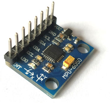
Pin-Out details of MPU6050:

| Pin | Usage |
| Vcc | Provides power for the module, can be +3V to +5V. Typically +5V is used |
| Ground | Connected to Ground of system |
| Serial Clock (SCL) | Used for providing clock pulse for I2C Communication |
| Serial Data (SDA) | Used for transferring Data through I2C communication |
| Auxiliary Serial Data (XDA) | Can be used to interface other I2C modules with MPU6050 |
| Auxiliary Serial Clock (XCL) | Can be used to interface other I2C modules with MPU6050 |
| AD0 | If more than one MPU6050 is used a single MCU, then this pin can be used to vary the address |
| Interrupt (INT) | Interrupt pin to indicate that data is available for MCU to read |
Flex Sensor

Flex Sensors are nothing but a variable resistor. The flex sensor resistance changes when the sensor is bent. They are usually available in two sizes 2.2 inches and 4.5 inches.
Why we use flex sensors in our project?
In this Gesture controlled Robotic Arm, a flex sensor is used to control the gripper of the robotic arm. When the flex sensor on the hand glove is bent, the servo motor attached to the gripper rotates and the gripper opens.

Flex sensors can be useful in many applications and we have built few projects using Flex sensor like a game controller, Tone generator, etc.
Getting ready the 3D printed Robotic ARM:

The 3D printed Robotic Arm used in this tutorial was made by following the design given by EEZYbotARM which is available in the Thingiverse. The complete procedure for making the 3D printed robotic arm and the assembling detail with video is present in the Thingiverse link, which is shared above.
Above is the image of my 3D printed Robotic Arm after assembling with 4 Servo Motors.
Components Required:
- Arduino Nano
- Flex Sensor
- 10k Resistor
- MPU6050
- Hand Gloves
- Connecting Wires
- Breadboard
Circuit Diagram:
The following image shows the circuit connections for Arduino based gesture controlled Robotic Arm.

Circuit Connection between MPU6050 & Arduino Nano:
|
MPU6050 |
Arduino Nano |
|
VCC |
+5V |
|
GND |
GND |
|
SDA |
A4 |
|
SCL |
A5 |
Circuit Connection between Servo Motors & Arduino Nano:
|
Arduino Nano |
SERVO MOTOR |
Power Adapter |
|
D2 |
Servo 1 Orange (PWM Pin) |
- |
|
D3 |
Servo 2 Orange (PWM Pin) |
- |
|
D4 |
Servo 3 Orange (PWM Pin) |
- |
|
D5 |
Servo 4 Orange (PWM Pin) |
- |
|
GND |
Servo 1,2,3,4 Brown (GND Pin) |
GND |
|
- |
Servo 1,2,3,4 Red (+5V Pin) |
+5V |
A flex sensor contains two pins. It doesn’t contain polarized terminals. So the pin one P1 is connected to the Arduino Nano’s Analog Pin A0 with a pull-up resistor of 10k and the pin two P2 is grounded to Arduino.
Mounting MPU6050 & Flex Sensor to Gloves
We have mounted the MPU6050 and Flex Sensor on to a hand glove. Here a wired connection is used to connect Glove and robotic arm but it can be made wireless by using an RF connection or a Bluetooth connection.
After every connection, the final setup for gesture-controlled Robotic Arm looks like the below image:
Programming Arduino Nano for Robotic Arm
As usual, complete code along with a working video is given at the end of this tutorial. Here a few important lines of code are explained.
1. First, include the necessary library files. Wire.h library is used for I2C communication between Arduino Nano & MPU6050 and servo.h for controlling servo motor.
#include<Wire.h>
#include<Servo.h>
2. Next, the objects for the class servo is declared. As we use four servo motors, four objects such as servo_1, servo_2, servo_3, servo_4 are created.
Servo servo_1;
Servo servo_2;
Servo servo_3;
Servo servo_4;
3. Next, the I2C address of MPU6050 & the variables to be used is declared.
const int MPU_addr=0x68; //MPU6050 I2C Address int16_t axis_X,axis_Y,axis_Z; int minVal=265; int maxVal=402; double x; double y; double z;
4. Next in the void setup, a baud rate of 9600 is set for Serial communication.
Serial.begin(9600);
And I2C communication between the Arduino Nano & MPU6050 is established:
  Wire.begin();                      //Initilize I2C Communication
  Wire.beginTransmission(MPU_addr);  //Start communication with MPU6050
  Wire.write(0x6B);                  //Writes to Register 6B
  Wire.write(0);                     //Writes 0 into 6B Register to Reset
  Wire.endTransmission(true);        //Ends I2C transmission
Also, four PWM pins are defined for servo motor connections.
  servo_1.attach(2);   // Forward/Reverse_Motor
  servo_2.attach(3);   // Up/Down_Motor
  servo_3.attach(4);   // Gripper_Motor
  servo_4.attach(5);   // Left/Right_Motor
5. Next in the void loop function, again establish I2C connection between the MPU6050 and Arduino Nano and then start to read the X, Y, Z-Axis data from the register of MPU6050 and store them in corresponding variables.
  Wire.beginTransmission(MPU_addr);
  Wire.write(0x3B);                  //Start with regsiter 0x3B
  Wire.endTransmission(false);
  Wire.requestFrom(MPU_addr,14,true);  //Read 14 Registers
                         axis_X=Wire.read()<<8|Wire.read();
                         axis_Y=Wire.read()<<8|Wire.read();
                         axis_Z=Wire.read()<<8|Wire.read();
After that, map the min and max value of the axis data from the MPU6050 sensor in the range of -90 to 90.
                        int xAng = map(axis_X,minVal,maxVal,-90,90);
                        int yAng = map(axis_Y,minVal,maxVal,-90,90);
                        int zAng = map(axis_Z,minVal,maxVal,-90,90);
Then use the following formula to calculate the x, y, z values in terms of 0 to 360.
  x= RAD_TO_DEG * (atan2(-yAng, -zAng)+PI);
  y= RAD_TO_DEG * (atan2(-xAng, -zAng)+PI);
                          z= RAD_TO_DEG * (atan2(-yAng, -xAng)+PI);
Then read the flex sensor Analog output data at the Arduino Nano’s A0 pin and according to the digital value of the flex sensor set the servo angle of the gripper. So if the flex sensor data is greater than 750 the servo motor angle of the gripper is 0 degree and if less than 750 it is 180 degrees.
  int gripper;
  int flex_sensorip = analogRead(A0);
  if(flex_sensorip > 750)
        {
          gripper = 0;
        }
        else
        {
          gripper = 180;
        }
   servo_3.write(gripper);
Then the movement of MPU6050 on the X-axis from 0 to 60 is mapped in terms of 0 to 90 degrees for the servo motor’s Forward/Reverse motion the Robotic arm.
    if(x >=0 && x <= 60)
  {
     int mov1 = map(x,0,60,0,90);
     Serial.print("Movement in F/R = ");
     Serial.print(mov1);
     Serial.println((char)176);
     servo_1.write(mov1);
  }
And the movement of MPU6050 on the X-axis from 250 to 360 is mapped in terms of 0 to 90 degrees for the servo motor’s UP/DOWN motion Robotic arm.
  else if(x >=300 && x <= 360)
  {
     int mov2 = map(x,360,250,0,90);
     Serial.print("Movement in Up/Down = ");
     Serial.print(mov2);
     Serial.println((char)176);
     servo_2.write(mov2);
  }
Movement of MPU6050 on the Y-axis from 0 to 60 is mapped in terms of 90 to 180 degrees for the servo motor’s Left Movement of the Robotic arm.
 if(y >=0 && y <= 60)
  {
     int mov3 = map(y,0,60,90,180);
     Serial.print("Movement in Left = ");
     Serial.print(mov3);
     Serial.println((char)176);
     servo_4.write(mov3);
  }
Movement of MPU6050 in the Y-axis from 300 to 360 is mapped in terms of 0 to 90 degrees for the servo motor’s Right Movement of the Robotic arm.
  else if(y >=300 && y <= 360)
  {
     int mov3 = map(y,360,300,90,0);
     Serial.print("Movement in Right = ");
     Serial.print(mov3);
     Serial.println((char)176);
     servo_4.write(mov3);
  }
Working of Gesture controlled Robotic Arm using Arduino

Finally, upload the code to Arduino Nano and wear the hand glove mounted with the MPU6050 & Flex Sensor.
1. Now move the hand down to move the robotic arm forward and move up to move the robotic arm up.
2. Then tilt the hand left or right to turn the robotic arm left or right.
3. Bend the flex cable attached with the hand glove’s finger to open the gripper and then release it to close it.
The complete working is demonstrated in the video given below.
Complete Project Code
//Code for Gesture Controlled Robotic ARM (Arduino Nano & MPU6050)

//Circuit Digest
#include<Wire.h>                //I2C Wire Library

#include<Servo.h>               //Servo Motor Library
Servo servo_1;

Servo servo_2;

Servo servo_3;

Servo servo_4;
const int MPU_addr=0x68;        //MPU6050 I2C Address

int16_t axis_X,axis_Y,axis_Z;

int minVal=265;

int maxVal=402;
double x;

double y;

double z;


void setup()

{

  Serial.begin(9600);


  Wire.begin();                      //Initilize I2C Communication

  Wire.beginTransmission(MPU_addr);  //Start communication with MPU6050

  Wire.write(0x6B);                  //Writes to Register 6B

  Wire.write(0);                     //Writes 0 into 6B Register to Reset

  Wire.endTransmission(true);        //Ends I2C transmission


  servo_1.attach(2);   // Forward/Reverse_Motor

  servo_2.attach(3);   // Up/Down_Motor

  servo_3.attach(4);   // Gripper_Motor

  servo_4.attach(5);   // Left/Right_Motor


}
void loop()

{

  Wire.beginTransmission(MPU_addr);

  Wire.write(0x3B);                  //Start with regsiter 0x3B

  Wire.endTransmission(false);

  Wire.requestFrom(MPU_addr,14,true);  //Read 14 Registers


  axis_X=Wire.read()<<8|Wire.read();                //Reads the MPU6050 X,Y,Z AXIS Value

  axis_Y=Wire.read()<<8|Wire.read();

  axis_Z=Wire.read()<<8|Wire.read();


  int xAng = map(axis_X,minVal,maxVal,-90,90);     // Maps axis values in terms of -90 to +90

  int yAng = map(axis_Y,minVal,maxVal,-90,90);

  int zAng = map(axis_Z,minVal,maxVal,-90,90);


  x= RAD_TO_DEG * (atan2(-yAng, -zAng)+PI);       //Formula to convert into degree

  y= RAD_TO_DEG * (atan2(-xAng, -zAng)+PI);

  z= RAD_TO_DEG * (atan2(-yAng, -xAng)+PI);
  int gripper;

  int flex_sensorip = analogRead(A0);            //Reads flex sensor output


  if(flex_sensorip > 750)

        {

          gripper = 0;

        }

        else

        {

          gripper = 180;

        }


   servo_3.write(gripper);                    //Writes gripper value to 3rd servo motor


  if(x >=0 && x <= 60)

  {

     int mov1 = map(x,0,60,0,90);

     Serial.print("Movement in F/R = ");

     Serial.print(mov1);

     Serial.println((char)176);

     servo_1.write(mov1);

  }


  else if(x >=300 && x <= 360)

  {

     int mov2 = map(x,360,250,0,180);

     Serial.print("Movement in Up/Down = ");

     Serial.print(mov2);

     Serial.println((char)176);

     servo_2.write(mov2);

  }
 if(y >=0 && y <= 60)

  {

     int mov3 = map(y,0,60,90,180);

     Serial.print("Movement in Left = ");

     Serial.print(mov3);

     Serial.println((char)176);

     servo_4.write(mov3);

  }


  else if(y >=300 && y <= 360)

  {

     int mov3 = map(y,360,300,90,0);

     Serial.print("Movement in Right = ");

     Serial.print(mov3);

     Serial.println((char)176);

     servo_4.write(mov3);

  }

}
