
In our previous tutorial learned about SPI communication in Arduino. Today we will learn about another Serial Communication Protocol: I2C (Inter Integrated Circuits). Comparing I2C with SPI, I2C has only two wires while SPI uses four, and I2C can have Multiple masters and slaves, while SPI can have only one master and multiple slaves. So there are more than one microcontrollers in a project that need to be masters, then I2C is used. I2C communication is generally used to communicate with Gyroscope, accelerometer, barometric pressure sensors, LED displays, etc.
In this Arduino I2C tutorial, we will use I2C communication between two Arduino boards and send (0 to 127) values to each other by using a potentiometer. Values will be displayed on the 16x2 LCD connected to each of the Arduinos. Here, one Arduino will act as the Master and another one will act as the Slave. So let’s start with the introduction of communication between two Arduino using I2C.
Table of Contents
- What is the I2C Communication Protocol?
- How does I2C Communication Between Two Arduino Boards Work?
- Where to use I2C Communication Between Arduinos?
- I2C in Arduino: Pin Configuration and Setup
- Components Required For Arduino I2C Tutorial
- Circuit Diagram
- Working Explanation of Communication between two Arduino using I2C
- I2C Programming in Arduino
- Master Arduino Programming Explanation
- Slave Arduino Programming Explanation
- Technical Summary and GitHub Repository
- Frequently Asked Questions
- Projects Related to Arduino-to-Arduino Communication
What is the I2C Communication Protocol?
The term IIC stands for “Inter Integrated Circuits”. It is normally denoted as I2C or I squared C or even as 2-wire interface protocol (TWI) at some places, but it all means the same. I2C is a synchronous communication protocol, meaning, both the devices that share the information must share a common clock signal. It has only two wires to share information out of which one is used for the cock signal and the other is used for sending and receiving data.
How does I2C Communication Between Two Arduino Boards Work?
I2C communication was first introduced by Philips. As said earlier, it has two wires, these two wires will be connected across two devices. Here, one device is called a master, and the other device is called a slave. Communication should and will always occur between two a Master and a Slave. The advantage of I2C communication is that more than one slave can be connected to a Master.
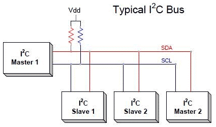
The complete communication takes place through these two wires, namely, Serial Clock (SCL) and Serial Data (SDA).
Serial Clock (SCL): Shares the clock signal generated by the master with the slave
Serial Data (SDA): Sends the data to and from between the Master and slave.
At any given time, only the master will be able to initiate the communication. Since there is more than one slave in the bus, the master has to refer to each slave using a different address. When addressed, only the slave with that particular address will reply back with the information, while the others quit. This way, we can use the same bus to communicate with I2C between Arduinos.
The voltage levels of I2C are not predefined. I2C communication is flexible, which means the device that is powered by 5V, can use 5V for I2C, and the 3.3V devices can use 3v for I2C communication. But what if two devices that are running on different voltages, need to communicate using I2C? A 5V I2C bus can’t be connected to a 3.3V device. In this case , voltage shifters are used to match the voltage levels between two I2C buses.
There is a set of conditions that frame a transaction. Initialization of transmission begins with a falling edge of SDA, which is defined as ‘START’ condition in the diagram below, where the master leaves SCL high while setting SDA low.
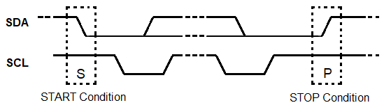
As shown in the diagram above below,
The falling edge of SDA is the hardware trigger for the START condition. After this, all devices on the same bus go into listening mode.
In the same manner, the rising edge of SDA stops the transmission, which is shown as ‘STOP’ condition in the above diagram, where the master leaves SCL high and also releases SDA to go HIGH. So the rising edge of SDA stops the transmission.

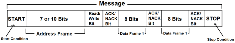
R/W bit indicates the direction of transmission of the following bytes, if it is HIGH means the slave will transmit, and if it is low means the master will transmit.
Each bit is transmitted on each clock cycle, so it takes 8 clock cycles to transmit a byte. After each byte either sent or received, the ninth clock cycle is held for the ACK/NACK (acknowledged/not acknowledged). This ACK bit is generated by either the slave or the master, depending on the situation. For the ACK bit, SDA is set to low by the master or slave at the 9th clock cycle. So it is low, it is considered as an ACK otherwise NACK.
Where to use I2C Communication Between Arduinos?
I2C communication is used only for short-distance communication. It is certainly reliable to an extent since it has a synchronised clock pulse to make it smart. This protocol is mainly used to communicate with sensor or other devices which has to send information to a master. It is very handy when a microcontroller has to communicate with many other slave modules using a minimum of only wires. If you are looking for a long-range communication, you should try RS232, and if you are looking for more reliable communication, you should try the SPI protocol.
I2C in Arduino: Pin Configuration and Setup
The image below shows the I2C pins present in Arduino UNO.
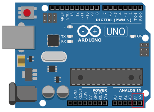
I2C Line | Pin in Arduino |
SDA | A4 |
SCL | A5 |
Before we get started into programming I2C using two Arduinos. We need to learn about the Wire library used in Arduino IDE.
The library <Wire.h> is included in the program to use the following functions for I2C communication.
1. Wire.begin(address):
Use: This library is used for making communication with I2C devices. This Initiate the Wire library and join the I2C bus as a master or slave.
Address: The 7-bit slave address is optional, and if the address is not specified, it joins the bus as a master like this [Wire.begin()].
2. Wire.read():
Use: This function is used to read a byte that was received from a master or slave device, either that was transmitted from a slave device to a master device after a call to requestFrom() or was transmitted from a master to a slave.
3. Wire.write():
Use: This function is used to write data to a slave or master device.
Slave to Master: Slave writes data to a master when the Wire.RequestFrom() is used in the master.
Master to Slave: For transmission from a master to a slave device, Wire.write() is used in-between calls to Wire.beginTransmission() and Wire.endTransmission().
Wire.write() can be written as:
- Wire.write(value)
value: a value to send as a single byte.
- Wire.write(string) :
string: a string to send as a series of bytes.
- Wire.write(data, length):
data: an array of data to send as bytes
length: the number of bytes to transmit.
4. Wire.beginTransmission(address):
Use: This function is used to begin a transmission to the I2C device with the given slave address. Subsequently, build a queue of bytes for transmission with the write() function and then transmit them by calling the endTransmission() function. The 7-bit address of the device is transmitted.
5. Wire.endTransmission();
Use: This function is used to end a transmission to a slave device that was begun by beginTransmission() and transmits the bytes that were queued by Wire.write().
6. Wire.onRequest();
Use: This function gets called when a master requests data using Wire.requestFrom() from the slave device. Here we can include Wire.write() function to send data to the master.
Use: This function gets called when a slave device receives a data from a master. Here we can include Wire.read(); function to read the data sent from the master.
8. Wire.requestFrom(address,quantity);
Use: This function is used in the master to request bytes from a slave device. The function Wire.read() is used to read the data sent from the slave device.
address: the 7-bit address of the device to request bytes from
quantity: the number of bytes to request
Components Required For Arduino I2C Tutorial
- Arduino Uno (2-Nos)
- 16X2 LCD display module
- 10K Potentiometer (4-Nos)
- Breadboard
- Connecting Wires
Circuit Diagram

Working Explanation of Communication between two Arduino using I2C
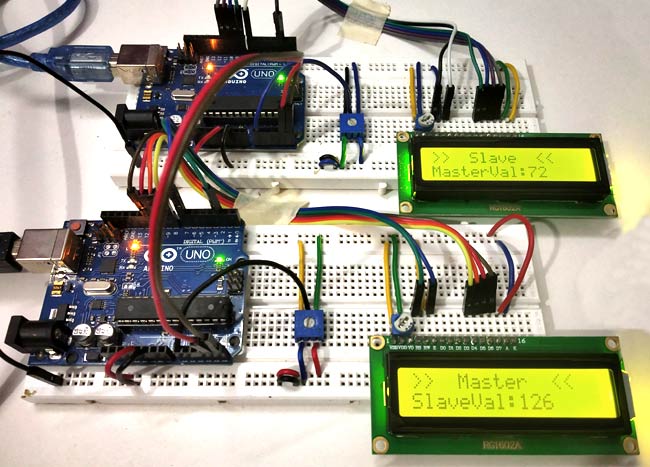
Here for demonstrating I2C communication in Arduino, we use Two Arduino UNO with Two 16X2 LCD display attached to each other and use two potentiometers at both arduino to determine the sending values (0 to 127) from master to slave and slave to master by varying the potentiometer.
We take input analog value at arduino pin A0 from (0 to 5V) by using potentiometer and convert them into Analog to Digital value (0 to 1023). Then these ADC values are further converted into (0 to 127) as we can send only 7-bit data through I2C communication. The I2C communication takes place through two wires at pin A4 & A5 of both arduino.
Values at Slave Arduino’s LCD will be changed by varying the POT at master side and vice versa.
I2C Programming in Arduino
This tutorial has two programs, one for the master Arduino and the other for the slave Arduino. Complete programs for both the sides are given at the end of this project with a demonstration Video.
Master Arduino Programming Explanation
1. First of all we need to include the Wire library for using I2C communication functions and the LCD library for using LCD functions. Also, define LCD pins for a 16x2 LCD. Learn more about interfacing an LCD with Arduino here.
#include<Wire.h>
#include<LiquidCrystal.h>
LiquidCrystal lcd(2, 7, 8, 9, 10, 11);
2. In void setup()
- We Start Serial Communication at Baud Rate 9600.
Serial.begin(9600);
- Next we start the I2C communication at pin (A4,A5)
Wire.begin(); //Begins I2C communication at pin (A4,A5)
- Next, we initialize the LCD display module in 16X2 mode and display the welcome message and clear after five seconds.
  lcd.begin(16,2);                           //Initilize LCD display
  lcd.setCursor(0,0);                        //Sets Cursor at first line of Display
  lcd.print("Circuit Digest");               //Prints CIRCUIT DIGEST in LCD
  lcd.setCursor(0,1);                        //Sets Cursor at second line of Display
  lcd.print("I2C 2 ARDUINO");                //Prints I2C ARDUINO in LCD
  delay(5000);                               //Delay for 5 seconds
  lcd.clear();                               //Clears LCD display
3. In void loop()
- First, we need to get data from the Slave, so we use requestFrom() with the slave address 8, and we request one byte
Wire.requestFrom(8,1);
The received value is read using Wire.read()
byte MasterReceive = Wire.read();
- Next we need to read the analog value from the master Arduino POT attached to pin A0
int potvalue = analogRead(A0);
We convert that value in terms of one byte as 0 to 127.
byte MasterSend = map(potvalue,0,1023,0,127);
- Next we need to send those converted values so we begin the transmission with slave arduino with 8 address
Wire.beginTransmission(8);
Wire.write(MasterSend);
 Wire.endTransmission();
- Next, we display those received values from the slave Arduino with a delay of 500 microseconds, and we continuously receive and display those values.
lcd.setCursor(0,0);            //Sets Currsor at line one of LCD
lcd.print(">>  Master  <<");      //Prints >> Master << at LCD
lcd.setCursor(0,1);                      //Sets Cursor at line two of LCD
lcd.print("SlaveVal:");                //Prints SlaveVal: in LCD
lcd.print(MasterReceive);  //Prints MasterReceive in LCD received from Slave
Serial.println("Master Received From Slave");    //Prints in Serial Monitor
Serial.println(MasterReceive);
delay(500);
lcd.clear();
Slave Arduino Programming Explanation
1. Same as master, first of all we need to include the Wire library for using I2C communication functions and the LCD library for using LCD functions. Also, define LCD pins for a 16x2 LCD.
#include<Wire.h>
#include<LiquidCrystal.h>
LiquidCrystal lcd(2, 7, 8, 9, 10, 11);
2. In void setup()
- We Start Serial Communication at a Baud Rate of 9600.
Serial.begin(9600);
- Next we start the I2C communication at pins (A4, A5) with the slave address as 8. Here, it is important to specify the slave address.
Wire.begin(8);
Next, we need to call the function when the Slave receives a value from the master and when the Master requestsa value from the Slave
Wire.onReceive(receiveEvent);
Wire.onRequest(requestEvent);
- Next, we initialize the LCD module in 16X2 mode and display the welcome message and clear after five seconds.
  lcd.begin(16,2);                           //Initilize LCD display
  lcd.setCursor(0,0);                        //Sets Cursor at first line of Display
  lcd.print("Circuit Digest");               //Prints CIRCUIT DIGEST in LCD
  lcd.setCursor(0,1);                        //Sets Cursor at second line of Display
  lcd.print("I2C 2 ARDUINO");                //Prints I2C ARDUINO in LCD
  delay(5000);                               //Delay for 5 seconds
  lcd.clear();                               //Clears LCD display
3. Next, we have two functions, one for the request event and one for the receive event
For the request Event
When the Master requests a value from the slave, this function will be executed. This function takes input value from the Slave POT and converts it in terms of 7-bit and sends that value to the master.
void requestEvent()
{
  int potvalue = analogRead(A0);
  byte SlaveSend = map(potvalue,0,1023,0,127);
  Wire.write(SlaveSend);
}
For Receive Event
When Master sends data to the slave with the slave address (8) this function will be executed. This function reads the received value from the master and stores it in a variable of type byte.
void receiveEvent (int howMany
{
 SlaveReceived = Wire.read();
}
4. In Void loop():
We display the received value from the master continuously in the LCD module.
void loop(void)
{
  lcd.setCursor(0,0);                              //Sets Currsor at line one of LCD
  lcd.print(">>  Slave  <<");                      //Prints >> Slave << at LCD
  lcd.setCursor(0,1);                              //Sets Cursor at line two of LCD
  lcd.print("MasterVal:");                         //Prints MasterVal: in LCD
  lcd.print(SlaveReceived);                        //Prints SlaveReceived value in LCD received from Master
  Serial.println("Slave Received From Master:");   //Prints in Serial Monitor
  Serial.println(SlaveReceived);
  delay(500);
  lcd.clear();
}
By rotating the Potentiometer at one side, you can see the varying values on the LCD on the other side:
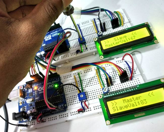
So this is how I2C communication takes place in Arduino, here we have used two Arduinos to demonstrate not only sending of data but also receiving the data using I2C communication. So now you can interface any I2C sensor to Arduino.
Technical Summary and GitHub Repository
Understand the core functionality and components used in this project. Browse the full implementation and files on GitHub to learn how the project is done and the working principle.


Frequently Asked Questions
⇥ How can two Arduino boards be connected via serial communication?
Connecting their SDA (data) and SCL (clock) lines, two Arduino Uno boards can be connected in the context of I²C, a type of see rial communication. One board is configured in master mode and the other in slave mode on the Uno, with SDA being A4 and SCL being A5. The Wire library functions are used to start requests and transmissions to control data transfer.
⇥ What function do pull-up resistors on the SDA and SCL lines serve in I²C communication?
Devices using I²C's open-drain bus can only pull lines low; they are unable to drive them high. When no device is actively pulling the lines low, pull-up resistors on the SDA and SCL make sure the lines return to HIGH (idle). This avoids floating lines and en ables dependable multi-device communication.
⇥ When two Arduino UNO boards are connected, which pins are used for SDA and SCL?
The specific I²C pins on the Arduino Uno are:
Analog pin A4 → SDA
Analog pin A5 → SCL
The entire I²C communication interface is made up of these two wires
Projects Related to Arduino-to-Arduino Communication
Learn how various communication protocols allow Arduinos to share data efficiently. These projects cover everything from Bluetooth for wireless messaging to I2C for sensor data. They assist you in comprehending the benefits and drawbacks of every protocol in practical situations.
 in Arduino to Communication between two Arduino Boards")
How to use SPI (Serial Peripheral Interface) in Arduino to Communication between two Arduino Boards
In this tutorial, we learn about the SPI protocol and how to use it in Arduino. We will use SPI Protocol for communication between two Arduinos. Here one Arduino will act as Master and another one will act as Slave, two LEDs and push buttons will be connected to both the Arduino.

Long Distance Wired Serial Communication with Arduino using RS485 and CAT Cables
In this tutorial, we are going to learn about the RS485 communication protocol and how to implement it with the two Arduino Nano we have with us and how to use the MAX485 RS485 to UART conversion Module.

I2C Communication on STM8S using Cosmic C Compiler – Reading MLX90614 Sensor Temperature Values
In this article, we are going to perform the I2C Communication on the STM8S microcontroller by using the MLX90614 I2C sensor. We will measure the Ambient Temperature and the Object’s Temperature, and then we will display the measured temperature on the LCD.
The complete coding for the Master and Slave Arduino is given below, with a demonstration video
Complete Project Code
Master Arduino Programming
//I2C MASTER CODE
//I2C Communication between Two Arduino
//Circuit Digest
//Pramoth.T
#include<Wire.h>                             //Library for I2C Communication functions
#include<LiquidCrystal.h>                    //Library for LCD display function
LiquidCrystal lcd(2, 7, 8, 9, 10, 11);       //Define LCD Module Pins (RS,EN,D4,D5,D6,D7)

 void setup()
{
  lcd.begin(16,2);                           //Initilize LCD display
  lcd.setCursor(0,0);                        //Sets Cursor at first line of Display
  lcd.print("Circuit Digest");               //Prints CIRCUIT DIGEST in LCD
  lcd.setCursor(0,1);                        //Sets Cursor at second line of Display
  lcd.print("I2C 2 ARDUINO");                //Prints I2C ARDUINO in LCD
  delay(5000);                               //Delay for 5 seconds
  lcd.clear();                               //Clears LCD display
  Serial.begin(9600);                        //Begins Serial Communication at 9600 baud rate
  Wire.begin();                              //Begins I2C communication at pin (A4,A5)
}

void loop()
{
    Wire.requestFrom(8,1);                           // request 1 byte from slave arduino (8)
    byte MasterReceive = Wire.read();                // receive a byte from the slave arduino and store in MasterReceive
    int potvalue = analogRead(A0);                   // Reads analog value from POT (0-5V)
    byte MasterSend = map(potvalue,0,1023,0,127);    //Convert digital value (0 to 1023) to (0 to 127)

    Wire.beginTransmission(8);                       // start transmit to slave arduino (8)
    Wire.write(MasterSend);                          // sends one byte converted POT value to slave
    Wire.endTransmission();                          // stop transmitting
    lcd.setCursor(0,0);                              //Sets Currsor at line one of LCD
    lcd.print(">>  Master  <<");                     //Prints >> Master << at LCD
    lcd.setCursor(0,1);                              //Sets Cursor at line two of LCD
    lcd.print("SlaveVal:");                          //Prints SlaveVal: in LCD
    lcd.print(MasterReceive);                        //Prints MasterReceive in LCD received from Slave
    Serial.println("Master Received From Slave");    //Prints in Serial Monitor
    Serial.println(MasterReceive);
    delay(500);
    lcd.clear();

}

Slave Arduino Programming
//I2C SLAVE CODE
//I2C Communication between Two Arduino
//CircuitDigest
//Pramoth.T
#include<Wire.h>                          //Library for I2C Communication functions
#include<LiquidCrystal.h>                 //Library for LCD display function
LiquidCrystal lcd(2, 7, 8, 9, 10, 11);    //Define LCD Module Pins (RS,EN,D4,D5,D6,D7)
byte SlaveReceived = 0;
void setup()
{
  lcd.begin(16,2);                        //Initilize LCD display
  lcd.setCursor(0,0);                     //Sets Cursor at first line of Display
  lcd.print("Circuit Digest");            //Prints CIRCUIT DIGEST in LCD
  lcd.setCursor(0,1);                     //Sets Cursor at second line of Display
  lcd.print("I2C 2 ARDUINO");             //Prints I2C ARDUINO in LCD
  delay(5000);                            //Delay for 5 seconds
  lcd.clear();                            //Clears LCD display
  Serial.begin(9600);                     //Begins Serial Communication at 9600 baud rate
  Wire.begin(8);                          //Begins I2C communication with Slave Address as 8 at pin (A4,A5)
  Wire.onReceive(receiveEvent);           //Function call when Slave receives value from master
  Wire.onRequest(requestEvent);           //Function call when Master request value from Slave
}
void loop(void)
{
  lcd.setCursor(0,0);                              //Sets Currsor at line one of LCD
  lcd.print(">>  Slave  <<");                      //Prints >> Slave << at LCD
  lcd.setCursor(0,1);                              //Sets Cursor at line two of LCD
  lcd.print("MasterVal:");                         //Prints MasterVal: in LCD
  lcd.print(SlaveReceived);                        //Prints SlaveReceived value in LCD received from Master
  Serial.println("Slave Received From Master:");   //Prints in Serial Monitor
  Serial.println(SlaveReceived);
  delay(500);
  lcd.clear();

}
void receiveEvent (int howMany)                    //This Function is called when Slave receives value from master
{
   SlaveReceived = Wire.read();                    //Used to read value received from master and store in variable SlaveReceived
}
void requestEvent()                                //This Function is called when Master wants value from slave
{
  int potvalue = analogRead(A0);                   // Reads analog value from POT (0-5V)
  byte SlaveSend = map(potvalue,0,1023,0,127);    // Convert potvalue digital value (0 to 1023) to (0 to 127)
  Wire.write(SlaveSend);                          // sends one byte converted POT value to master
}
Comments
I did not see any I2C bus pull up resistors. Why?
Also, where did the address 8 come from?
Did you just make it up since you are working in an isolated environment?

I'm working a similar project I've connected all the sensors and LCD to a common VCC and GND with both Arduinos .. When i power the first Arduino with the USB the second Arduino is powering up..is this right and safe or not?... Do i have to separate the two 5V pins and power the two arduinos individually?...and divide the sensors VCC among both Arduinos?