
Choosing a communication protocol for communication between microcontrollers and peripheral devices is an important part of embedded system. It is important because the overall performance of any embedded application depends on communication means as it is related to cost reduction, faster data transfer, long distance coverage etc.
In the previous tutorials we have learned about I2C communication protocol and SPI Communication protocols in Arduino. Now there is another serial communication protocol called RS-485.This Protocol uses an asynchronous serial communication. The main advantage of RS-485 is the long distance data transfer between two devices. And they are most commonly used in electrically noisy industrial environment.
In this tutorial, we will learn about RS-485 Serial communication between two Arduinos and then demonstrate it by controlling the brightness of the LED connected to a Slave Arduino from Master Arduino by sending ADC values through RS-485 Module. A 10k potentiometer is used to vary the ADC values at Master Arduino.
Let’s start by understanding the working of RS-485 Serial communication.
RS-485 Serial Communication Protocol
RS-485 is an asynchronous serial communication protocol which doesn’t require clock pulse. It uses a technique called differential signal to transfer binary data from one device to another.
So what is this differential signal transfer method??
Differential signal method works by creating a differential voltage by using a positive and negative 5V. It provides a Half-Duplex communication when using two wires and Full-Duplex requires 4 fours wires.
By using this method
- RS-485 supports higher data transfer rate of 30Mbps maximum.
- It also provides maximum data transfer distance compared to RS-232 protocol. It transfers data up to 1200 meters maximum.
- The main advantage of RS-485 over RS-232 is the multiple slave with single Master while RS-232 supports only single slave.
- It can have a maximum of 32 devices connected to RS-485 protocol.
- Another advantage of the RS-485 is that it is immune to the noise as they use differential signal method to transfer.
- RS-485 is faster compared to I2C protocol.
RS-485 in Arduino
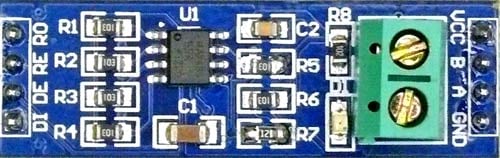
For using RS-485 in Arduino, a module called 5V MAX485 TTL to RS485 which is based on Maxim MAX485 IC is needed as it allows serial communication over long distance of 1200 meters and it is bidirectional. In half duplex mode it has a data transfer rate of 2. 5Mbps.
5V MAX485 TTL to RS485 module requires a voltage of 5V and uses 5V logic levels so that it can be interfaced with hardware serial ports of microcontrollers like Arduino.
It has following features:
- Operating voltage: 5V
- On-board MAX485 chip
- A low power consumption for the RS485 communication
- Slew-rate limited transceiver
- 5.08mm pitch 2P terminal
- Convenient RS-485 communication wiring
- All pins of chip have been lead to can be controlled through the microcontroller
- Board size: 44 x 14mm
Pin-Out of RS-485:
|
Pin Name |
Use |
|
VCC |
5V |
|
A |
Non-inverting Receiver Input Non-Inverting Driver Output |
|
B |
Inverting Receiver Input Inverting Driver Output |
|
GND |
GND (0V) |
|
R0 |
Receiver Out (RX pin) |
|
RE |
Receiver Output (LOW-Enable) |
|
DE |
Driver Output (HIGH-Enable) |
|
DI |
Driver Input (TX pin) |
This RS-485 module can be easily interfaced with Arduino. Let’s use the hardware serial ports of Arduino 0 (RX) and 1(TX) (In UNO, NANO). Programming is also simple just use the Serial.print() to write to RS-485 and Serial.Read() to read from RS-485.
Programming part is explained later in detail but first lets check the required components and circuit diagram.
Components Required
- Arduino UNO or Arduino NANO (2)
- MAX485 TTL to RS485 Converter Module - (2)
- 10K Potentiometer
- 16x2 LCD Display
- LED
- Breadboard
- Connecting Wires
In this tutorial Arduino Uno is used as Master and Arduino Nano is used as Slave. Two Arduino Boards are used here so two RS-485 Modules are required.
Circuit Diagram

Circuit Connection between first RS-485 and Arduino UNO (Master):
|
RS-485 |
Arduino UNO |
|
DI |
1 (TX) |
|
DE RE |
8 |
|
R0 |
0 (RX) |
|
VCC |
5V |
|
GND |
GND |
|
A |
To A of Slave RS-485 |
|
B |
To B of Slave RS-485 |
Connection between second RS-485 and Arduino Nano (Slave):
|
RS-485 |
Arduino UNO |
|
DI |
D1 (TX) |
|
DE RE |
D8 |
|
R0 |
D0 (RX) |
|
VCC |
5V |
|
GND |
GND |
|
A |
To A of Master RS-485 |
|
B |
To B of Master RS-485 |
Circuit Connection between a 16x2 LCD and Arduino Nano:
|
16x2 LCD |
Arduino Nano |
|
VSS |
GND |
|
VDD |
+5V |
|
V0 |
To potentiometer centre pin for contrast control of LCD |
|
RS |
D2 |
|
RW |
GND |
|
E |
D3 |
|
D4 |
D4 |
|
D5 |
D5 |
|
D6 |
D6 |
|
D7 |
D7 |
|
A |
+5V |
|
K |
GND |
A 10K potentiometer is connected to the Analog Pin A0 of the Arduino UNO for providing Analog input and a LED is connected to pin D10 of Arduino Nano.
Programming Arduino UNO & Arduino Nano for RS485 Serial Communication
For programming both boards Arduino IDE is used. But make sure you have selected the corresponding PORT from Tools->Port and Board from Tools->Board.
Complete code with a Demo Video is given at the end of this tutorial. Here we are explaining important part of the code. There are two programs in this tutorial, one for Arduino UNO (Master) and other for Arduino Nano (Slave).
Code Explanation for Master: Arduino UNO
In the Master side, just simply take Analog input at pin A0 by varying the potentiometer and then SerialWrite those values to the RS-485 bus through the Hardware Serial Ports (0,1) of Arduino UNO.
To Begin Serial Communication at Hardware Serial Pins (0,1) use:
Serial.begin(9600);
To read Analog value at the pin A0 of Arduino UNO and store them in a variable potval use:
int potval = analogRead(pushval);
Before writing the potval value to serial port, pins DE & RE of RS-485 should be HIGH that is connected to the pin 8 of Arduino UNO so to Make pin 8 HIGH:
digitalWrite(enablePin, HIGH);
Next to put those values in the Serial Port connected with the RS-485 module, use the following statement
Serial.println(potval);
Code Explanation for Slave: Arduino NANO
In the Slave side an integer value is received from the Master RS-485 that is available at the Hardware Serial port of the Arduino Nano (Pins -0,1). Simply read those value and store in a variable. The values are in form of (0 -1023). So it is converted into (0-255) as PWM technique is used to control LED brightness.
Then AnalogWrite those converted value to the LED pin D10 (It’s a PWM pin). So depending upon the PWM value the brightness of the LED changes and also display those values in 16x2 LCD display.
In order for the Slave Arduino‘s RS-485 to receive the values from the Master, just make the pins DE & RE of RS-485 LOW. So the pin D8 (enablePin) of Arduino NANO is made LOW.
digitalWrite(enablePin, LOW);
And to read the integer data available at Serial Port and store them in a variable use
int pwmval = Serial.parseInt();
Next convert value from (0-1023 to 0-255) and store them in a variable:
int convert = map(pwmval,0,1023,0,255);
Next write the analog value (PWM) to pin D10 where LED anode is connected:
analogWrite(ledpin,convert);
To print those PWM value in 16x2 LCD display use
lcd.setCursor(0,0);
lcd.print("PWM FROM MASTER");
lcd.setCursor(0,1);
lcd.print(convert);
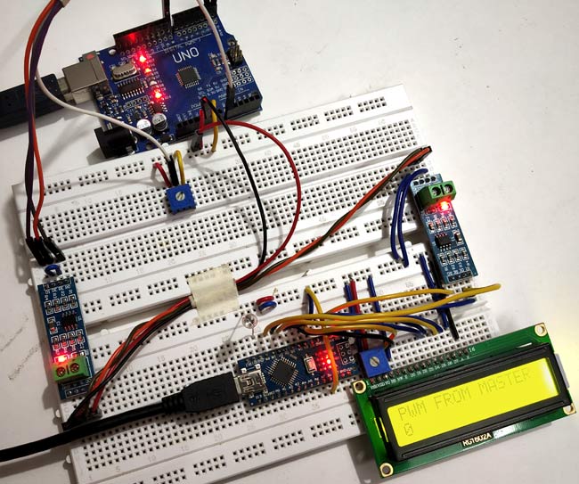
Controlling LED Brightness with Serial Communication RS485
When the PWM value is set at 0 using potentiometer, the LED is turned OFF.
And when PWM value is set at 251 using potentiometer: The LED is turned ON with full brightness as shown in below picture:
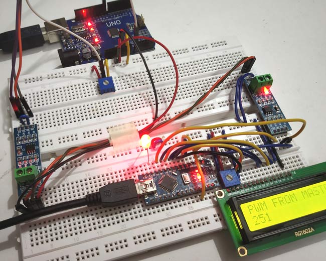
So this is how RS485 can be used for serial communication in Arduino.
Complete Project Code
Master (Arduino UNO):
//Master code (Arduino UNO)

//Serial Communication Between Arduino using RS-485
int enablePin = 8;

int pushval = A0;

int potval =0 ;

void setup()

{

  Serial.begin(9600);            // initialize serial at baudrate 9600:

  pinMode(enablePin, OUTPUT);

  pinMode(pushval,INPUT);

  delay(10);

  digitalWrite(enablePin, HIGH);  //  (always high as Master Writes data to Slave)

}

void loop()

{

    int potval = analogRead(pushval);

    Serial.println(potval);          //Serial Write POTval to RS-485 Bus

    delay(100);

}
SLAVE CODE: (Arduino NANO):
//Slave code (Arduino NANO)

//Serial Communication Between Two Arduinos using RS-485

//Circuit Digest
#include <LiquidCrystal.h>          //Include LCD library for using LCD display functions
int enablePin = 8;

int ledpin = 10;
LiquidCrystal lcd(2,3,4,5,6,7);       // Define LCD display pins RS,E,D4,D5,D6,D7
void setup()

{

  lcd.begin(16,2);

  lcd.print("CIRCUIT DIGEST");

  lcd.setCursor(0,1);

  lcd.print("RS485 ARDUINO");

  delay(3000);

  lcd.clear();

  Serial.begin(9600);                   // initialize serial at baudrate 9600:

  pinMode(ledpin,OUTPUT);

  pinMode(enablePin, OUTPUT);

  delay(10);

  digitalWrite(enablePin, LOW);        //  (Pin 8 always LOW to receive value from Master)


}
void loop()
{

  while (Serial.available())                   //While have data at Serial port this loop executes

     {

        lcd.clear();

        int pwmval = Serial.parseInt();            //Receive INTEGER value from Master throught RS-485

        int convert = map(pwmval,0,1023,0,255);    //Map those value from (0-1023) to (0-255)

        analogWrite(ledpin,convert);               //PWM write to LED

        lcd.setCursor(0,0);

        lcd.print("PWM FROM MASTER");

        lcd.setCursor(0,1);

        lcd.print(convert);                        //Displays the PWM value

        delay(100);

    }

 }

Hi there, I have tried to make this circuit myself using your code and diagrams. I cannot replicate the success that you are having. Is there any help you could give me? I have triple checked my connections, but I am using an arduino mega as a slave, not an arduino nano. Please advise