
RS232 Communication Protocol represents one of the most successful and enduring standards in electronics history. Originally developed in 1962 by the Electronic Industries Association (EIA), RS232 defined the interface between Data Terminal Equipment (DTE) and Data Communication Equipment (DCE) for serial binary data interchange. While modern protocols like RS485, SPI, I2C, and CAN offer advanced features, RS232's simplicity and reliability ensure its continued relevance in industrial automation, embedded systems, and legacy equipment integration.
This comprehensive guide covers everything from basic RS232 principles to advanced implementation techniques, helping both beginners and experienced engineers master this essential communication protocol.
Table of Contents
- What is Serial Communication?
- Current RS232 Standards: TIA-232-F Specification
- What is RS232?
- RS232 vs Modern Communication Protocols
- Enhanced Electrical Specifications (TIA-232-F Standard)
- How RS232 Works?
- Mechanical Specification
- What is Handshaking?
- RS232 Implementation Examples and Best Practices
- Applications of RS232 Communication
- RS232 Troubleshooting Guide
- Frequently Asked Questions About RS232
- Conclusion: RS232's Enduring Legacy in Modern Electronics
RS232 (Recommended Standard 232) is one of the most enduring serial communication protocols in electronics, introduced in 1960 and still widely used today in industrial automation, embedded systems, and legacy equipment. Despite being over 60 years old, RS232 remains a cornerstone technology for reliable point-to-point communication in countless applications worldwide.
The protocol has evolved from its original purpose of connecting electromechanical teletypewriters to modems, and now serves as a critical interface in modern industrial systems, medical devices, scientific instruments, and legacy system integration. Understanding RS232 is essential for engineers working with embedded systems, industrial automation, and serial communication protocols.
Why RS232 Matters in 2025: Still widely used in industrial PLCs, CNC machines, and automation systems • Essential for interfacing with legacy equipment worth billions of dollars • Offers superior noise immunity compared to TTL/CMOS signals • Simple, cost-effective solution for point-to-point communication • Compatible across different manufacturers and decades of equipment.
What is Serial Communication?
In telecommunication, the process of sending data sequentially over a computer bus is called as serial communication, which means the data will be transmitted bit by bit. While in parallel communication the data is transmitted in a byte (8 bit) or character on several data lines or buses at a time. Serial communication is slower than parallel communication but used for long data transmission due to lower cost and practical reasons.


Example to understand:
Serial communication – you are shooting a target using machine guns, where bullets reach one by one to the target.
Parallel communication - you are shooting a target using a shotgun, where a large number of the bullets reach at the same time.
Modes of Data Transfer in Serial Communication:
Asynchronous Data Transfer – The mode in which the bits of data are not synchronized by a clock pulse. Clock pulse is a signal used for synchronization of operation in an electronic system.
Synchronous Data Transfer – The mode in which the bits of data are synchronized by a clock pulse.
Characteristics of Serial Communication:
Baud rate is used to measure the speed of transmission. It is described as the number of bits passing in one second. For example, if the baud rate is 200 then 200 bits per Sec passed. In telephone lines, the baud rates will be 14400, 28800 and 33600.
Stop Bits are used for a single packet to stop the transmission which is denoted as “T”. Some typical values are 1, 1.5 & 2 bits.
Parity Bit is the simplest form of checking the errors. There are of four kinds, i.e., even odd, marked and spaced. For example, If 011 is a number the parity bit=0, i.e., even parity and the parity=1, i.e., odd parity.
Current RS232 Standards: TIA-232-F Specification
While commonly referred to as RS232, the current official standard is TIA-232-F (Telecommunications Industry Association), published in 1997. This specification superseded the earlier EIA-232 standards and represents the most recent revision of the protocol.
Evolution of RS232 Standards:
RS-232 (1962): Original standard by Electronic Industries Association
RS-232-C (1969): Most widely referenced version with 25-pin specification
EIA-232-D (1987): Updated electrical characteristics
EIA-232-E (1991): Enhanced noise immunity specifications
TIA-232-F (1997): Current standard with improved cable length definitions
Key Updates in TIA-232-F:
Cable Length: Now defined by capacitance per unit length rather than fixed distance
Signal Quality: Enhanced specifications for signal integrity and noise immunity
Compatibility: Maintained backward compatibility with all previous versions
Manufacturing: Updated to accommodate modern semiconductor processes
Technical Note: Despite the official name change to TIA-232-F, the term "RS232" remains universally used in industry documentation, datasheets, and engineering discussions. Both terms refer to the same communication standard.
What is RS232?
RS232C "Recommended Standard 232C" was a widely-used version featuring 25-pin connectors, while RS232D introduced 22-pin configurations. Modern implementations typically use 9-pin D-type male connectors (DB9) which include the most essential signals for practical communication. The current TIA-232-F standard maintains compatibility with all previous connector configurations while providing enhanced electrical specifications.
RS232 is a standard protocol used for serial communication, it is used for connecting computer and its peripheral devices to allow serial data exchange between them. As it obtains the voltage for the path used for the data exchange between the devices. It is used in serial communication up to 50 feet with the rate of 1.492kbps. As EIA defines, the RS232 is used for connecting Data Transmission Equipment (DTE) and Data Communication Equipment (DCE).

Universal Asynchronous Data Receiver &Transmitter (UART) used in connection with RS232 for transferring data between printer and computer. The microcontrollers are not able to handle such kind of voltage levels, connectors are connected between RS232 signals. These connectors are known as the DB-9 Connector as a serial port and they are of two type’s Male connector (DTE) & Female connector (DCE).
RS232 vs Modern Communication Protocols
Understanding how RS232 compares to modern communication standards helps determine when to use each protocol. While newer technologies offer advanced features, RS232's unique characteristics make it irreplaceable in specific applications.
RS232 vs RS485: Detailed Comparison
Both protocols serve different communication needs. For an in-depth analysis, see our comprehensive RS485 vs RS232 comparison guide.
| Feature | RS232 | RS485 |
| Network Topology | Point-to-point only | Multi-drop (up to 32 devices) |
| Maximum Distance | 15m (standard), 1000m (low baud) | 1200m at standard rates |
| Maximum Speed | 1 Mbps (short distance) | 10 Mbps (short distance) |
| Voltage Levels | ±12V (single-ended) | ±5V (differential) |
| Noise Immunity | Good | Excellent (differential signaling) |
| Duplex Mode | Full duplex | Half duplex |
| Implementation Cost | Very low | Low to moderate |
RS232 vs USB: When to Choose Each
Choose RS232 When:
Working with legacy industrial equipment and PLCs
Need simple, reliable point-to-point communication
Operating in electrically noisy industrial environments
Requiring deterministic, low-latency communication
Budget constraints favor low-cost, simple solutions
Interfacing with scientific instruments and test equipment
Choose USB When:
Need high-speed data transfer (480 Mbps to 10 Gbps)
Want plug-and-play device recognition
Require power delivery to connected devices (up to 100W)
Working with modern consumer electronics
Need to connect multiple devices via hubs
Developing portable or mobile applications
Why RS232 Survives in 2025
Despite being over 60 years old, RS232 remains relevant for several compelling reasons:
Simplicity: Minimal hardware requirements and straightforward implementation
Reliability: Proven technology with decades of field-tested performance
Deterministic Behavior: Predictable timing without complex protocol overhead
Universal Compatibility: Supported across all manufacturers and platforms
Legacy Equipment Value: Billions of dollars in existing industrial infrastructure
Electromagnetic Compatibility: Better noise immunity than TTL/CMOS for industrial environments
Real-time Performance: No protocol negotiation delays or complex handshaking
Modern RS232 Applications (2025):
Industrial Automation: PLC programming and monitoring interfaces
Medical Devices: Patient monitoring and diagnostic equipment
Scientific Instruments: Laboratory equipment and measurement devices
Point-of-Sale Systems: Receipt printers, cash drawers, barcode scanners
Telecommunications: Console ports on network equipment
Embedded Systems: Debug interfaces and system configuration
For more information about various serial communication protocols and their applications, explore our comprehensive tutorials.
Enhanced Electrical Specifications (TIA-232-F Standard)
The electrical characteristics of RS232 are precisely defined to ensure reliable communication across different manufacturers and applications. Understanding these specifications is crucial for proper implementation and troubleshooting.
Voltage Level Specifications
| Signal Type | Logic State | Voltage Range | Typical Value |
| Data Signals | Logic 1 (Mark) | -3V to -15V | -12V |
| Data Signals | Logic 0 (Space) | +3V to +15V | +12V |
| Control Signals | Asserted (ON) | +3V to +15V | +12V |
| Control Signals | De-asserted (OFF) | -3V to -15V | -12V |
| Undefined Region | Invalid | -3V to +3V | Transition zone |
Important Note: RS232 uses negative logic for data signals, where negative voltage represents logic 1 and positive voltage represents logic 0. This is opposite to TTL/CMOS logic levels.
Performance Characteristics
Maximum Slew Rate: 30V/μsec (prevents crosstalk between adjacent signals)
Line Impedance: 3Ω to 7Ω (driver output impedance), 3kΩ to 7kΩ (receiver input impedance)
Maximum Bit Rate: 20 kbps (standard), up to 1 Mbps (short distances)
Operating Voltage: 250V AC maximum
Current Rating: 3 Amps maximum
Dielectric Withstanding Voltage: 1000 VAC minimum
Cable Length vs Baud Rate Relationship
| Baud Rate | Maximum Cable Length | Typical Application |
| 9600 bps | 1000m+ | Long-distance industrial communication |
| 19200 bps | 300m | Standard industrial automation |
| 38400 bps | 150m | Building automation systems |
| 115200 bps | 15m | Computer peripherals, development boards |
| 1 Mbps | 1-3m | High-speed local connections |
Environmental Operating Conditions
Operating Temperature: -40°C to +85°C (industrial grade)
Storage Temperature: -55°C to +125°C
Relative Humidity: 5% to 95% (non-condensing)
EMI/RFI Immunity: Good (better than TTL/CMOS signals)
ESD Protection: ±15kV (depending on interface IC)
Signal Quality and Integrity
Maintaining signal integrity is crucial for reliable RS232 communication, especially at higher baud rates and longer cable lengths:
Cable Capacitance: Maximum 2500pF (including connectors)
Rise/Fall Time: Controlled by slew rate limitation (30V/μsec)
Jitter Tolerance: Typically ±4% of bit time
Common Mode Rejection: Depends on ground differential (keep <2V)
Best Practices for Signal Integrity:
Use twisted-pair cables for differential noise reduction
Implement proper shielding in electrically noisy environments
Maintain good ground connections between communicating devices
Consider using ferrite cores on cables in high-EMI environments
Keep cable lengths as short as practical for the application
Design Consideration: Modern RS232 implementations often use interface ICs like MAX232, MAX3232, or SP3232 to convert between TTL/CMOS logic levels (0V/3.3V or 0V/5V) and RS232 voltage levels (±12V). These chips also provide ESD protection and reduce power consumption compared to discrete implementations.
The ratings and specifications may vary with different equipment models and manufacturers. Always consult specific device datasheets for exact parameters.
How RS232 Works?
RS232 works on the two-way communication that exchanges data to one another. There are two devices connected to each other, (DTE) Data Transmission Equipment& (DCE) Data Communication Equipment which has the pins like TXD, RXD, and RTS& CTS. Now, from DTE source, the RTS generates the request to send the data. Then from the other side DCE, the CTS, clears the path for receiving the data. After clearing a path, it will give a signal to RTS of the DTE source to send the signal. Then the bits are transmitted from DTE to DCE. Now again from DCE source, the request can be generated by RTS and CTS of DTE sources clears the path for receiving the data and gives a signal to send the data. This is the whole process through which data transmission takes place.
TXD | TRANSMITTER |
RXD | RECEIVER |
RTS | REQUEST TO SEND |
CTS | CLEAR TO SEND |
GND | GROUND |
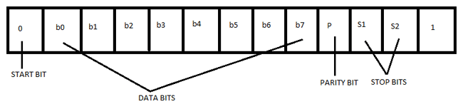
For example: The signals set to logic 1, i.e., -12V. The data transmission starts from next bit and to inform this, DTE sends start bit to DCE. The start bit is always ‘0’, i.e., +12 V & next 5 to 9 characters is data bits. If we use parity bit, then 8 bits data can be transmitted whereas if parity doesn’t use, then 9 bits are being transmitted. The stop bits are sent by the transmitter whose values are 1, 1.5 or 2 bits after the data transmission.
Mechanical Specification
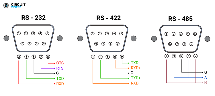
For mechanical specifications, we have to study about two types of connectors that is DB-25 and DB-9. In DB-25, there are 25 pins available which are used for many of the applications, but some of the applications didn’t use the whole 25 pins. So, the 9 pin connector is made for the convenience of the devices and equipments.
Now, here we are discussing the DB-9 pin connector which is used for connection between microcontrollers and connector. These are of two types: Male Connector (DTE) & Female Connector (DCE). There are 5 pins on the top row and 4 pins in the bottom row. It is often called DE-9 or D-type connector.
Pin Structure of DB-9 Connector:


Pin Description DB-9 Connector:
PIN No. | Pin Name | Pin Description |
1 | CD (Carrier Detect) | Incoming signal from DCE |
2 | RD (Receive Data) | Receives incoming data from DTE |
3 | TD (Transmit Data) | Send outgoing data to DCE |
4 | DTR (Data Terminal Ready) | Outgoing handshaking signal |
5 | GND (Signal ground) | Common reference voltage |
6 | DSR (Data Set Ready) | Incoming handshaking signal |
7 | RTS (Request to Send) | Outgoing signal for controlling flow |
8 | CTS (Clear to Send) | Incoming signal for controlling flow |
9 | RI (Ring Indicator) | Incoming signal from DCE |
Understanding these pin configurations is crucial for proper cable wiring. For comparison with other industrial protocols, see our detailed RS485 vs RS232 analysis which covers when to choose each protocol for your application.
What is Handshaking?
How can a transmitter, transmits and the receiver receives data successfully. So, the Handshaking defines, for this reason.
Handshaking is the process which is used to transfer the signal from DTE to DCE to make the connection before the actual transfer of data. The messaging between transmitter & receiver can be done by handshaking.
There are 3 types of handshaking processes named as:-
No Handshaking:
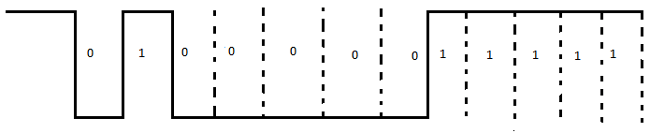
If there is no handshaking, then DCE reads the already received data while DTE transmits the next data. All the received data stored in a memory location known as receiver’s buffer. This buffer can only store one bit so receiver must read the memory buffer before the next bit arrives. If the receiver is not able to read the stored bit in the buffer and next bit arrives then the stored bit will be lost.
As shown in below diagram, a receiver was unable to read the 4th bit till the 5th bit arrival and this result overriding of 4th bit by 5th bit and 4th bit is lost.

Hardware Handshaking:
It uses specific serial ports, i.e., RTS & CTS to control data flow.
In this process, transmitter asks the receiver that it is ready to receive data then receiver checks the buffer that it is empty, if it is empty then it will give signal to the transmitter that I am ready to receive data.
The receiver gives the signal to transmitter not to send any data while already received data cannot be read.
Its working process is same as above described in handshaking.
Software Handshaking:
In this process, there are two forms, i.e., X-ON & X-OFF. Here, ‘X’ is the transmitter.
X-ON is the part in which it resumes the data transmission.
X-OFF is the part in which it pauses the data transmission.
It is used to control the data flow and prevent loss during transmission.

RS232 Implementation Examples and Best Practices
Understanding practical RS232 implementation helps bridge the gap between theory and real-world applications. These examples demonstrate common scenarios and proper techniques for reliable communication. We have previous build many RS232 based projects here at circuidigest you can check out RS232 communication between Atmega8 and Arduino UNO, RS232 communication with PIC microcontroller, RS232 communication between two ATmega8.
Basic Microcontroller to PC Communication
The most common RS232 implementation involves connecting a microcontroller to a PC for debugging, data logging, or configuration purposes.
Hardware Requirements:
Microcontroller with UART capability (Arduino, STM32, PIC, etc.)
RS232 level converter IC (MAX232, MAX3232, SP3232)
DB9 connector and appropriate cable
Bypass capacitors (typically 1μF for MAX232)
Connection Steps:
Microcontroller UART Setup: Configure UART pins for desired baud rate (typically 9600 or 115200 bps)
Level Conversion: Connect microcontroller TX/RX to MAX232 TTL side
RS232 Interface: Connect MAX232 RS232 side to DB9 connector pins 2 and 3
Ground Connection: Ensure common ground between all components
Power Supply: Provide stable 3.3V or 5V to level converter IC
Software Configuration Example:
Baud Rate: 9600 bps (reliable for most applications)
Data Bits: 8
Parity: None
Stop Bits: 1
Flow Control: None (for simple applications)
Industrial PLC Communication Setup
Industrial applications require robust RS232 implementation with proper shielding and surge protection.
Design Considerations:
Cable Selection: Use shielded twisted-pair cables (22-24 AWG)
Connector Type: Industrial DB9 connectors with locking mechanisms
Grounding: Single-point grounding to prevent ground loops
EMI Protection: Ferrite cores on cables near high-power equipment
Surge Protection: RS232 surge protectors for outdoor installations
Typical Industrial Settings:
| Application | Baud Rate | Cable Length | Special Requirements |
| PLC to HMI | 9600-19200 bps | 10-50 meters | Shielded cable, industrial connectors |
| CNC Machine Interface | 9600-38400 bps | 5-15 meters | High-reliability connectors, EMI filtering |
| Building Automation | 9600 bps | 100-500 meters | Low baud rate for distance, surge protection |
| Scientific Instruments | 1200-9600 bps | 10-100 meters | Precision timing, low noise environment |
Common RS232 Interface ICs and Selection
Choosing the right RS232 interface IC is crucial for reliable operation and proper voltage level conversion.
Popular RS232 Interface ICs:
MAX232: Classic dual RS232 driver/receiver, requires external capacitors, ±5V supply
MAX3232: 3.3V operation, lower power consumption, integrated charge pump
SP3232: Pin-compatible with MAX3232, enhanced ESD protection (±15kV)
MAX13232: Ultra-low power, 1μA shutdown mode, automotive grade
ICL3232: Industrial temperature range (-40°C to +85°C), robust design
IC Selection Criteria:
Supply Voltage: Match microcontroller voltage (3.3V or 5V)
Power Consumption: Important for battery-powered applications
ESD Protection: Critical for industrial and automotive use
Temperature Range: Must meet environmental requirements
Package Type: Consider PCB space constraints and assembly method
Cable Specifications and Recommendations
Proper cable selection significantly impacts RS232 communication reliability, especially in industrial environments. You can also check out this long distance wired Arduino communication using cables, where we have used RS485.
Cable Types:
Standard Cable: Unshielded, suitable for office environments, distances <3 meters
Shielded Cable: Foil or braid shield, industrial environments, distances <15 meters
Low-Capacitance Cable: Special dielectric, high-speed applications, <50pF/foot
Industrial Cable: Heavy-duty jacket, multiple shielding, harsh environments
Recommended Cable Specifications:
| Parameter | Standard Application | Industrial Application |
| Wire Gauge | 24-28 AWG | 22-24 AWG |
| Capacitance | <30 pF/foot | <25 pF/foot |
| Impedance | 100-120 Ω | 120 Ω nominal |
| Shielding | Optional | Required (foil + braid) |
| Jacket Material | PVC | PVC, PUR, or TPE |
RS232 to Modern Interface Conversion
Many applications require converting RS232 to modern interfaces like USB, Ethernet, or WiFi for integration with contemporary systems.
FTDI-based: FT232R, FT232H chips - excellent driver support, reliable operation
Prolific-based: PL2303 chips - lower cost, adequate for basic applications
Silicon Labs: CP2102, CP2104 chips - good balance of cost and performance
Selection Tips: Choose FTDI for critical applications, ensure proper driver support
Ethernet to RS232 Converters:
Enable remote access to RS232 devices over network
Useful for distributed industrial systems
Support multiple simultaneous connections
Often include web-based configuration interfaces
Best Practices for Reliable RS232 Implementation
Hardware Best Practices:
Grounding: Use single-point grounding, avoid ground loops
Power Supply: Ensure clean, stable power with proper decoupling
PCB Layout: Keep RS232 traces short, separate from switching circuits
Connectors: Use quality connectors with proper pin retention
ESD Protection: Implement TVS diodes for exposed connections
Software Best Practices:
Error Handling: Implement timeout mechanisms and error recovery
Buffer Management: Use appropriate buffer sizes for data throughput
Flow Control: Implement when dealing with slow processing devices
Protocol Design: Include checksums and acknowledgments for critical data
Testing: Thoroughly test with various cable lengths and environmental conditions
Environmental Considerations:
Temperature: Ensure components operate within specified temperature ranges
Humidity: Protect connections from moisture ingress
Vibration: Use appropriate strain relief and secure mounting
EMI/RFI: Implement proper shielding and filtering as needed
For more advanced serial communication projects and comparisons with other protocols, explore our serial communication articles and practical implementation guides.
Applications of RS232 Communication
RS232 serial communication is used in old generation PCs for connecting the peripheral devices like mouse, printers, modem etc.
Nowadays, RS232 is replaced by advanced USB.
It is also used in PLC machines, CNC machines, and servo controllers because it is far cheaper.
It is still used by some microcontroller boards, receipt printers, point of sale system (PoS), etc.
RS232 Troubleshooting Guide
RS232 communication issues can stem from hardware problems, software configuration errors, or environmental factors. This systematic troubleshooting approach helps identify and resolve common problems quickly.
Common Communication Problems and Solutions
Problem 1: No Communication Between Devices
Symptoms: No data transmission, devices don't respond, timeout errors
Step-by-Step Diagnosis:
Verify Physical Connections:
Check cable continuity with multimeter (resistance should be <1Ω per wire)
Confirm TX pin connects to RX pin on opposite device
Ensure ground connection exists between both devices
Inspect connectors for bent pins or corrosion
Check Communication Parameters:
Verify identical baud rates on both devices
Match data bits (typically 8), parity (none/even/odd), stop bits (1 or 2)
Confirm flow control settings (none/hardware/software)
Check if devices use same character encoding (ASCII/Binary)
Test Signal Levels:
Measure TX voltage with multimeter: should be ±5V to ±15V
Check for proper voltage swing during data transmission
Verify ground potential difference <2V between devices
Problem 2: Intermittent Communication or Data Corruption
Symptoms: Occasional dropped characters, garbled data, checksum errors
Diagnostic Steps:
Cable and Environmental Issues:
Check cable length vs. baud rate specifications
Look for electromagnetic interference sources nearby
Verify cable shielding is properly grounded
Test in different physical locations to isolate EMI
Timing and Synchronization:
Reduce baud rate to test if timing is the issue
Check for clock drift between devices over time
Verify adequate processing time for receiving device
Power Supply Issues:
Measure supply voltage stability (should be within ±5%)
Check for voltage drops during peak current draw
Ensure adequate decoupling capacitors near RS232 ICs
Problem 3: One-Way Communication Only
Symptoms: Data flows in only one direction, echo tests fail
Solution Steps:
Check TX/RX pin connections (may be swapped)
Verify both devices have working transmitters and receivers
Test each direction separately with loop-back tests
Confirm both devices are configured for same duplex mode
RS232 Loop-Back Test Procedure
The loop-back test is the most effective way to verify RS232 port functionality and software configuration:
Equipment Needed:
Short piece of wire or jumper
Terminal software (PuTTY, HyperTerminal, or similar)
Multimeter (optional, for voltage verification)
Test Procedure:
Hardware Setup:
Power off both devices
Connect pin 2 (TX) to pin 3 (RX) on DB9 connector
For DB25: connect pin 2 (TX) to pin 3 (RX)
Ensure good electrical connection
Software Configuration:
Open terminal software and select correct COM port
Set baud rate (9600 is good for testing)
Configure: 8 data bits, no parity, 1 stop bit
Disable all handshaking (RTS/CTS and XON/XOFF)
Testing:
Type characters on keyboard
Each character should appear on screen (may appear twice if echo is enabled)
If no characters appear, check port settings and connections
Test with different baud rates if necessary
Interpreting Results:
Characters echo correctly: Port and software working properly
No characters appear: Wrong port, bad connection, or hardware failure
Garbled characters: Incorrect baud rate or electrical problems
Double characters: Software echo enabled (normal behavior)
Advanced Troubleshooting Tools
Oscilloscope Analysis:
Monitor signal quality and timing
Check for proper voltage levels (±12V typical)
Verify rise/fall times meet slew rate requirements
Look for noise, ringing, or distortion
Protocol Analyzers:
Capture and decode RS232 data streams
Identify timing violations and protocol errors
Monitor handshaking signals (RTS/CTS/DTR/DSR)
Useful for complex multi-device communication
Environmental Troubleshooting
Common Environmental Problems:
EMI/RFI Interference: Use shielded cables, ferrite cores, proper grounding
Ground Loops: Ensure single-point grounding, use isolation if necessary
Temperature Effects: Check operation at temperature extremes
Vibration: Secure connections, use strain relief on cables
Moisture: Protect connectors, use appropriate IP ratings
Industrial Environment Solutions:
Use industrial-grade connectors (M12, circular connectors)
Implement proper cable routing away from power lines
Consider RS232 isolators for ground loop elimination
Use surge protectors in lightning-prone areas
Software Configuration Checklist
| Parameter | Check | Common Values |
| COM Port | Correct port selected | COM1, COM2, /dev/ttyS0, /dev/ttyUSB0 |
| Baud Rate | Match both devices | 9600, 19200, 38400, 115200 |
| Data Bits | Usually 8 | 7, 8 |
| Parity | Match both devices | None, Even, Odd |
| Stop Bits | Usually 1 | 1, 1.5, 2 |
| Flow Control | Match or disable | None, Hardware (RTS/CTS), Software (XON/XOFF) |
Pro Tips for Faster Troubleshooting:
Always start with the simplest configuration (9600, 8, N, 1, no flow control)
Test with shortest possible cable first
Use known-good devices to isolate problems
Document working configurations for future reference
Keep spare cables and connectors for quick substitution testing
For more complex communication scenarios involving multiple devices, consider exploring RS485 communication protocols which offer better noise immunity and multi-drop capabilities.
Frequently Asked Questions About RS232
What is RS232 used for today in 2025?
RS232 remains widely used in industrial automation for PLC programming, medical equipment interfaces, scientific instruments, point-of-sale systems, and legacy equipment integration. It's particularly valuable in environments requiring simple, reliable point-to-point communication with excellent noise immunity. Many CNC machines, servo controllers, and building automation systems still rely on RS232 for critical communication functions.
What is the maximum distance for RS232 communication?
Standard RS232 supports up to 15 meters at maximum baud rates (115200 bps). However, at lower baud rates like 9600 bps, distances up to 1000 meters are achievable with proper cables. The actual distance depends on cable quality, environmental conditions, and acceptable error rates. Industrial applications often use 300-500 meters successfully at 9600-19200 baud rates.
What is the difference between DB9 and DB25 RS232 connectors?
DB25 connectors have 25 pins and support the complete RS232 specification including secondary channels and additional control signals. DB9 connectors have 9 pins covering the most commonly used signals (TX, RX, RTS, CTS, DTR, DSR, DCD, RI, and Ground). DB9 is more popular in modern applications due to its compact size and sufficient functionality for most use cases.
Can RS232 be converted to USB?
Yes, RS232 to USB converters are widely available and commonly used to connect legacy RS232 devices to modern computers lacking serial ports. These converters use USB-to-serial bridge chips and appear as virtual COM ports in the operating system. Quality varies significantly, so choose converters with proper driver support and FTDI or similar reliable chipsets.
What voltage levels does RS232 use?
RS232 uses ±12V signaling typically, with logic 1 (mark) represented by -3V to -15V and logic 0 (space) by +3V to +15V. The voltage region between -3V and +3V is undefined. This bipolar signaling provides better noise immunity compared to single-ended TTL/CMOS levels, making RS232 suitable for industrial environments.
Why is RS232 still used instead of USB or Ethernet?
RS232 offers several advantages: deterministic timing without protocol overhead, simplicity requiring minimal software, excellent EMI immunity, compatibility across decades of equipment, low cost implementation, and reliable operation in harsh industrial environments. Many legacy systems worth billions of dollars continue to use RS232, making it essential for system integration and maintenance.
What is the maximum baud rate for RS232?
The original RS232 standard specifies 20 kbps maximum, but modern implementations can achieve up to 1 Mbps over very short distances (1-3 meters). Practical maximum rates are typically 115200 bps for distances up to 15 meters. Higher rates require careful attention to cable quality, length, and electromagnetic interference.
How do I troubleshoot RS232 communication problems?
Start with a systematic approach: verify physical connections and cable continuity, confirm matching communication parameters (baud rate, data bits, parity, stop bits), test with loop-back connections, check voltage levels with a multimeter, and eliminate environmental interference sources. The loop-back test is particularly effective for isolating hardware vs. software issues.
What is the difference between RS232 and UART?
UART (Universal Asynchronous Receiver/Transmitter) is the digital logic circuit that handles serial communication at TTL/CMOS voltage levels (0V/3.3V or 0V/5V). RS232 is the physical interface standard that defines ±12V voltage levels, connectors, and cables. RS232 drivers/receivers convert between UART logic levels and RS232 voltage levels.
Can multiple devices connect to one RS232 port?
Standard RS232 is designed for point-to-point communication only. For multi-device networks, consider RS485 protocol which supports up to 32 devices on a single bus. Some RS232 multiplexers exist but add complexity and are not part of the standard specification.
What cables are needed for RS232 communication?
RS232 requires either straight-through cables (for DTE to DCE connections) or null-modem cables (for DTE to DTE connections). Use quality shielded cables for industrial environments and keep lengths appropriate for the baud rate. Standard DB9 to DB9 cables are most common for modern applications.
Is RS232 compatible with modern computers?
Most modern computers lack built-in RS232 ports, but USB-to-RS232 converters provide excellent compatibility. These adapters create virtual COM ports that work with existing RS232 software. For reliable industrial applications, choose converters with FTDI or similar proven chipsets and proper driver support.
Conclusion: RS232's Enduring Legacy in Modern Electronics
RS232 serial communication protocol has demonstrated remarkable longevity in the rapidly evolving world of electronics and communications. From its introduction in 1960 to the current TIA-232-F standard, RS232 has adapted to meet changing technological needs while maintaining its core strengths of simplicity, reliability, and universal compatibility.
Key Takeaways for Engineers and Developers
When to Choose RS232:
Legacy system integration and industrial automation applications
Point-to-point communication requiring deterministic timing
Harsh industrial environments needing robust, noise-immune communication
Cost-sensitive applications where simplicity is paramount
Scientific instruments and medical devices requiring proven reliability
Implementation Success Factors:
Proper voltage level conversion using quality interface ICs (MAX232, MAX3232)
Appropriate cable selection based on distance, speed, and environmental requirements
Correct connector pinout understanding (DB9/DB25 configurations)
Systematic troubleshooting approach using loop-back tests and signal analysis
Environmental considerations including EMI protection and proper grounding
RS232 in the Modern Technology Landscape
While newer protocols like RS485, USB, and Ethernet offer advanced features, RS232 continues to serve critical roles in:
Industrial Automation: PLC programming, HMI interfaces, and sensor communication
Scientific Research: Laboratory equipment control and data acquisition
Medical Technology: Patient monitoring systems and diagnostic equipment
Telecommunications: Network equipment console access and configuration
Embedded Systems: Debug interfaces and system programming
Future Outlook and Migration Strategies
As technology continues advancing, organizations must balance innovation with maintaining existing infrastructure. RS232 will likely remain relevant for:
Legacy Support: Billions of dollars in existing equipment requiring ongoing maintenance
Specialized Applications: Scenarios where simplicity and deterministic behavior are critical
Education: Teaching fundamental serial communication concepts
Prototyping: Quick development and testing of communication systems
Migration Considerations:
Evaluate USB-to-RS232 converters for modern computer integration
Consider RS485 protocol upgrades for multi-device networks
Implement Ethernet-to-RS232 gateways for remote access capabilities
Plan gradual transitions that maintain operational continuity
Final Recommendations
For engineers and developers working with RS232:
Master the Fundamentals: Understand voltage levels, timing, and connector configurations
Invest in Quality Tools: Good cables, connectors, and test equipment prevent many problems
Document Everything: Maintain clear records of working configurations and troubleshooting procedures
Stay Current: Keep up with modern conversion technologies and integration methods
Plan for the Future: Consider long-term maintenance and potential migration paths
RS232's six-decade journey from teletypewriter interfaces to modern industrial automation demonstrates the value of well-designed, standardized communication protocols. By understanding its principles, proper implementation techniques, and appropriate applications, engineers can continue leveraging this proven technology while preparing for future communication needs.
Whether you're maintaining legacy systems, developing new embedded applications, or integrating modern and traditional technologies, RS232 remains an essential tool in the electronics engineer's toolkit. Its combination of simplicity, reliability, and universal support ensures that RS232 will continue serving critical communication roles well into the future.
Continue exploring our comprehensive collection of serial communication tutorials and practical implementation guides to deepen your understanding of communication protocols and their applications in modern electronics.

There are various types of RS232 cables available in the market to convert it to other ports. Which are very usefull becuase it have solved problmens of various applications.
RS232 cables are used in the set top box , computer and weight machines and in very expensive machines too. The most widely used cable is RS232 to usb cable to communicate with other peripheral devices.