
In the domain of robotics and automation, precision-controlled mechanical movements have ushered in a revolutionary wave across diverse industries, spanning from manufacturing to healthcare. Thanks to the advent of cost-effective microcontrollers (Arduino) and easily accessible programming tools, enthusiasts and hobbyists now have the means to create their own Bluetooth-controllable robotic arm using an Arduino board, servo motors, and a motor driver.
Robotic arms have found their way into an extensive array of applications, from industrial automation to even Pick and Place assembly lines. The ARA (Arduino Robotic Arm), now, from the comfort of your own home, you can construct a Robot Arm mounted on a 2WD Arduino car kit.
This tutorial will serve as an illuminating guide on how to create an Arduino-powered Robotic Arm, replete with wireless control and programmability facilitated through a custom-build Android application. Within the application's interface, individual servos or axes of the robot arm can be manually maneuvered using dedicated buttons. Notably, this robot car encompasses two primary functions: a 2WD car mode and the control of a robotic arm. This integration is achieved through the utilization of two DC motors and a robotic arm. The robotic arm itself is presented through both a 3D-designed model (designed from scratch) and a physically assembled iteration.
Also, check our previously built Robotic Arm projects using different microcontrollers:
- DIY Pick and Place Robotic Arm using ARM7-LPC2148 ARM Microcontroller
- Hand Gesture Controlled Robotic Arm using Arduino Nano
- Arduino Based Robotic Arm
- Record and Play 3D Printed Robotic Arm using Arduino
- Robotic Arm Control using PIC Microcontroller
Kinematics of Arm Robot Manipulator
At first, the thought of building a robotic arm might sound complex and gruesome. But after learning the physics and kinematics behind it, and going more in-depth into the topic. You will understand that it is not that hard.
This robotic arm consists of 3 servo motors, 1 for the gripper and 2 for the arm joints movement. This means that the DOF (degree of freedom) for this robot is 2. The angle and position of the Arm depends on the kinematics.
Kinematics is the science that considers the motion of an object (robot) without cares for the cause of that motion. Kinematics studies the position, velocity, acceleration, and other higher derivatives of position with respect to time. Therefore, the study of kinematics refers to all geometrical and time-based properties of motion.
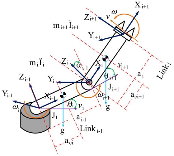
An arm robot manipulator is a set of links connected by joints, the lowest part is called the based, and the end part is called end-effector. The number of joints and how it moves define the degree of freedom (DOF). The joints are characterised as revolute or prismatic joints. Below fig shows a 2 DOF robot that consists of all revolute joints. A typical industrial robot has 5 or 6 joints. In this project, the kinematics and dynamics are derived from a 2-DOF system for the sake of simplicity.
Forward Kinematics
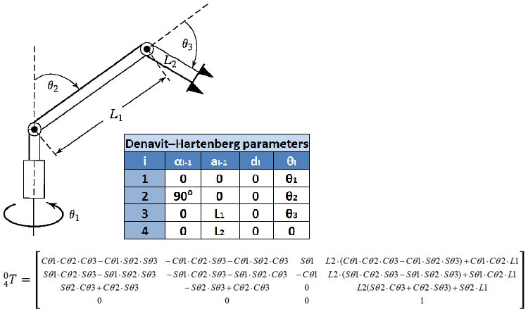
Forward kinematics involves utilizing a robot's kinematic equations to calculate the position of the end-effector based on given joint parameter values, which in this context are the positions of the servo motors. In the sketch of the robotic arm below, you can visualize the Denavit-Hartenberg parameters, an essential component in this process. Additionally, the derived forward kinematic equations for the robotic arm are presented.
While an alternative approach was ultimately pursued, one not reliant on matrices, the derived equations remain valuable for those interested in exploring different methodologies. It's important to note that 'C' represents cosine and 'S' represents sine.
Inverse Kinematics
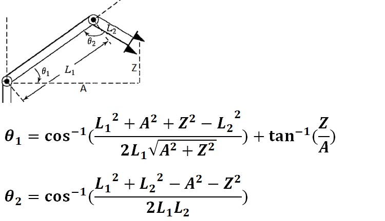
By solving the Inverse Kinematics equations, we can precisely control the movement and orientation of the robotic arm's end-effector. These equations provide us with the necessary angles for each joint to achieve a desired position in space. The figure below visually breaks down the variables that play a crucial role in these equations, allowing us to translate mathematical concepts into practical arm movements.
Design and Build of Robotic Arm
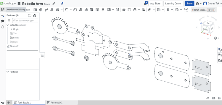
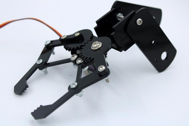
I created the custom robotic arm specifically for this project, and you can see screenshots of the CAD design I made using Onshape, as well as the actual mechanical arm I built, in the images below. If you're interested in recreating this project or incorporating my design into your own work, I've included the CAD .dxf files, which you can download from here.
For constructing the arm, I used laser-cut acrylic parts. However, if you have access to a 3D printer, you can also use that. If you opt for the 3D printing route, you'll need to open the files in SolidWorks, convert them to STL format, and save them. To do this, open any part, click 'Save As,' and choose STL as the file format.
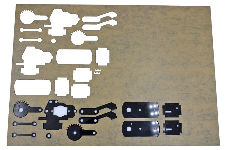
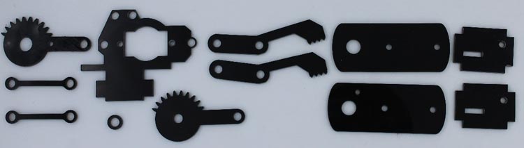
Here's a visual representation of what the laser-cut acrylic sheet will look like.
Arduino robot arms, much like other robot arms, are commonly evaluated based on their degrees of freedom (DOF). This term refers to the count of rotational joints integrated into the robot's design. The concept of DOF is interchangeable with the term "axes," a familiar term in this context. For instance, a 2DOF (2 Axis) robot arm is equipped with two distinct axes enabling specific motion.
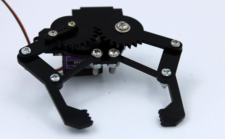
This robotic arm arrives in a flat-pack state, requiring minimal soldering for assembly and activation. It incorporates two MG90 servos, enabling two degrees of movement. Notably, it can adeptly grip lightweight objects using the gripper.
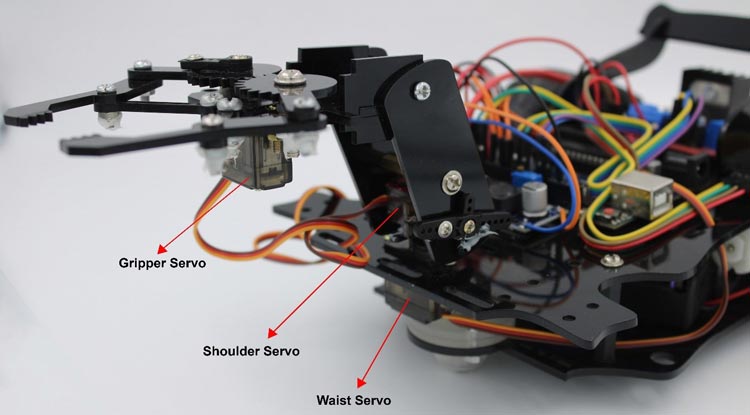
The "Base," also known as the "Waist," often facilitates a 180° or 360° rotation of the arm, contingent on the servo type employed (in this project, a 180° Servo was utilized).
The "Shoulder" maneuver is responsible for vertically raising or lowering the arm.
The "Gripper" engages by either opening or closing to "grab things."
Components Required for Robotic Arm Car
Arduino board (e.g., Arduino Uno)
MG 90 metal gear Servo motors (3x)
HC-05 Bluetooth module
Laser cut Chassis and Robotic arm mechanical components
12V Li-ion battery
LM2596 DC-DC Buck Converter
Switch
Jumper wires
Breadboard or PCB (Printed Circuit Board)
Screws, nuts, spacers
Assembly of Robotic Arm
We have utilized an acrylic sheet cut with a laser to create a Robotic Arm for our project. The sheet has been precisely cut to accommodate all the necessary fittings and components, allowing for easy assembly using screwdrivers.
Before starting the assembly, we need to adjust the angle adjustment of the servo motors. Otherwise, your robotic Arm will not work properly.
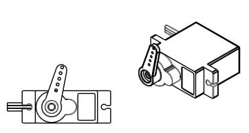
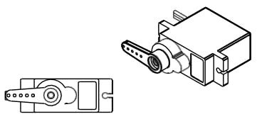
To begin, attach the Servo Arm to the servo by carefully aligning and securing it in place. We can manually calibrate and adjust the servo motor angle but some time manually calibration is not accurate or may not be possible. so you can calibrate your servo motors using the provided code #1. Refer to the circuit diagram mentioned below and connect your servo motors to Arduino pins 5, 6, and 3 accordingly. Upload the provided code #1 to your Arduino board, which will facilitate the calibration process. Failing to execute this step may result in unstable performance of your robot.
By ensuring proper alignment and calibration of the servos, you lay the foundation for a stable and well-functioning robot.
Angle values for robotic arm movements
No. | Servo type | Angle of rotation on servo(in°) | Information |
1 | Servo gripper | 150° | Pinch |
60° | Open | ||
2 | Servo Waist | 45° | Down |
90° | Up | ||
3 | Servo Base | 0° | Right position |
90° | Middle position | ||
180° | Left position |
This angle value may be changed according to your servo adjustment. After done with servo adjustments, you can pass Assembly stages.
Step 1: Here is an image showcasing all the essential components necessary for assembling the robotic arm.
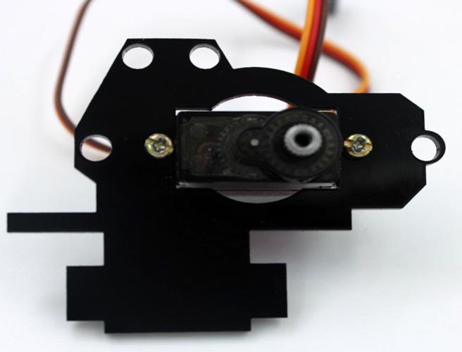
Step 2: Secure the servo motor to the gripper base plate using M2.5 10mm nuts and bolts.
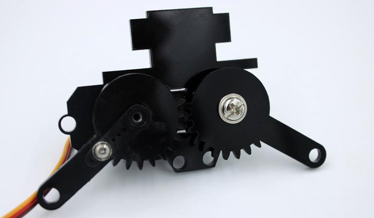
Step 3: Attach the pair of gripper gears to the servo and base plate using M4 10mm nuts and bolts.
Step 4: Secure the gripper hand to both gears at their designated positions using M3 30mm nuts and bolts.
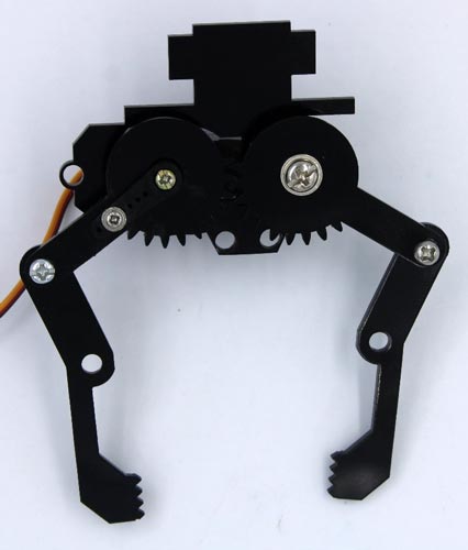
Step 5: Join the hand support link to both the gripper hand and servo base plate using M3 and M4 10mm nuts and bolts.
Step 6: Finally, attach the side stopper and shoulder movement legs to their respective positions using M3 nuts and bolts.
Circuit Diagram for Bluetooth-Controlled Robotic Arm Car with Arduino (3 Servo Motors)
In this setup, the DC motors work like the robot's wheels, helping it to move in different directions. Meanwhile, the three servo motors act like the robot arm's joints, allowing it to twist and turn at the waist, lift or lower its shoulder, and open or close its gripper.

For this project, you don't need any complicated wiring because all the motors use 5V. We control the motors using digital pins. We didn't use the 5V pin on the Arduino because it wouldn't give enough power to run all the motors well. Instead, we use a DC-DC buck converter and a different power supply. This way, we can provide enough power to make sure all the motors work properly.
Circuit Connection:
Arduino and L298N motor driver module Connections:
Connect the ground (GND) pin of the Arduino to the ground rail on the breadboard.
Connect the Vin pin of the Arduino to the positive rail on the breadboard.
Connect the 5V output from the LM2596 DC-DC buck converter to the positive rail on the breadboard.
Connect the ground (GND) output from the LM2596 DC-DC buck converter to the ground rail on the breadboard.
Connect the input 1 (IN1) and input 2 (IN2) pins of the L298N motor driver to two digital pins on the Arduino (e.g., pins 7 and 8) for controlling the first DC motor.
Connect the input 3 (IN3) and input 4 (IN4) pins of the L298N motor driver to two digital pins on the Arduino (e.g., pins 12 and 11) for controlling the second DC motor.
Connect the ENA and ENB pins of the L298N motor driver to on board high state pin of L298N motor driver.
Servo Motor Connections:
Connect the brown signal wire of the waist servo (first servo motor) to a digital pin on the Arduino (e.g., pin 5).
Connect the red positive wire of the waist servo to the positive rail on the breadboard.
Connect the black negative wire of the waist servo to the ground rail on the breadboard.
Connect the brown signal wire of the shoulder servo (second servo motor) to a digital pin on the Arduino (e.g., pin 6).
Connect the red positive wire of the shoulder servo to the positive rail on the breadboard.
Connect the black negative wire of the shoulder servo to the ground rail on the breadboard.
Connect the brown signal wire of the gripper servo (third servo motor) to a digital pin on the Arduino (e.g., pin 3).
Connect the red positive wire of the gripper servo to the positive rail on the breadboard.
Connect the black negative wire of the gripper servo to the ground rail on the breadboard.
Bluetooth Module Connections:
Connect the TX pin of the HC-05 Bluetooth module to the RX pin (digital pin 0) of the Arduino.
Connect the RX pin of the HC-05 Bluetooth module to the TX pin (digital pin 1) of the Arduino.
Connect the VCC pin of the HC-05 Bluetooth module to the 5V rail on the breadboard.
Connect the GND pin of the HC-05 Bluetooth module to the ground rail on the breadboard.
Power Connections:
Connect the positive terminal of the 12V Li-ion battery to the Vin input of the LM2596 DC-DC buck converter.
Connect the negative terminal of the battery to the ground rail on the breadboard.
Connect the positive terminal of the 12V Li-ion battery to the L298N motor driver module 12V input.
Connect the negative terminal of the battery to the GND of the L298N motor driver module.
When working with multiple servo motors, the power requirements exceed what the Arduino Uno microcontroller can provide. Therefore, an external power input is necessary. However, it is crucial to ensure that the input voltage does not exceed 5 volts to prevent damage to the Arduino microcontroller.
If using a higher-voltage battery, use a voltage-reducing circuit (DC - DC buck converter) to lower it to 5 volts. Connect the output of the voltage-reducing circuit to both the Arduino and servo motors. This ensures a safe and efficient power supply.
Additionally, make sure to configure the servo motor control and motor direction control in your Arduino code. Always double-check your connections before powering on the circuit.
Bluetooth-Controlled Robotic Arm Car Code Explanation
The Bluetooth-controlled robotic arm Car is controlled via an Android app on Smart phone. The app has different buttons for making the Car move forward, backward, left, and right. It also controls the robotic arm waist, shoulder, and gripper movements.
The app sends signals when pressed the specific button to the servo motors in the robot, telling them how to position the arm for each type of movement.
It is important to execute this code #1 before starting the assembly stages. This code is designed to calibrate and adjust the servo motors to their correct angles. By running this code, you can ensure that the servo motors are properly functioning and positioned accurately. This will help prevent any potential issues or complications during the subsequent stages of the assembly process.
Code #1
#include <ESP32_Servo.h>    // include servo library
// Define 3 Servos
Servo myServo1; // waist or base Servo
Servo myServo2; // shoulder Servo
Servo myServo3; // gripper Servo
void setup() {
  // Attach servos to Arduino PWM Pins
  myServo1.attach(5);
  myServo2.attach(6);
  myServo3.attach(3);
  myServo1.write(90);
  myServo2.write(90);
  myServo3.write(90);
}
void loop() {
}
This code #2 includes all the necessary servo motor movements to make your robot functional. Without this code, you will not be able to complete the project successfully. It is crucial for the proper operation of the robot.
This code outlines the setup and control mechanisms for a robotic arm and a 2WD Arduino car using servo motors and DC motors. It integrates Bluetooth communication to enable remote control and demonstrates how to manipulate servo angles and motor directions to achieve specific movements.
Code #2
#include <Servo.h>
Servo motor_1;
Servo motor_2;
Servo motor_3;
These lines include the necessary library for using servo motors and define three Servo objects (motor_1, motor_2, and motor_3) are created to control the three servos connected to pins 5, 6, and 3 respectively.
#define in1 7 //Motor1  L298 Pin in1
#define in2 8 //Motor1  L298 Pin in1
#define in3 12 //Motor2  L298 Pin in1
#define in4 11 //Motor2  L298 Pin in1
These lines define digital pins of Arduino (pin7,pin8,pin12 and pin11) for the L298N motor driver inputs to control the DC motors. The pins in1 and in2 control one motor, and the pins in3 and in4 control the other motor.
int servo1 = 90;
int servo2 = 0;
int servo3 = 90;
int bt_data;
int Speed = 130;
Initial positions (angles) for the three servos are set: servo1, servo2, and servo3. bt_data is used to store incoming Bluetooth data. Speed is initially set to 130.
void setup(){
Serial.begin(9600); // initialize serial communication at 9600 bits per second:
motor_1.attach(5);   // Waist Servo
motor_2.attach(6);   // Shoulder Servo
motor_3.attach(3);   // Gripper Servo
motor_1.write(servo1);
motor_2.write(servo2);
motor_3.write(servo3);
//pinMode(enA, OUTPUT); // declare as output for L298 Pin enA
pinMode(in1, OUTPUT); // declare as output for L298 Pin in1
pinMode(in2, OUTPUT); // declare as output for L298 Pin in2
pinMode(in3, OUTPUT); // declare as output for L298 Pin in3
pinMode(in4, OUTPUT); // declare as output for L298 Pin in4
//pinMode(enB, OUTPUT); // declare as output for L298 Pin enB
digitalWrite(in1, LOW); //Right Motor forword Pin
digitalWrite(in2, LOW); //Right Motor backword Pin
digitalWrite(in3, LOW); //Left Motor backword Pin
digitalWrite(in4, LOW); //Left Motor forword Pin
delay(1000);
}
In the setup() function, serial communication is initialized at 9600 bits per second. The servo motors are attached to specific pins, and their initial positions are set. The digital pins for motor control and the motor driver pins are set as outputs. The motor driver pins are initially set to low to ensure the motors are not moving during setup.
void loop(){
//if some date is sent, reads it and saves in state
if(Serial.available() > 0){
bt_data = Serial.read();
Serial.println(bt_data);
if(bt_data > 20)
{Speed = bt_data;}
}
The loop function is where the main program logic runs in a continuous loop.
This code block reads incoming Bluetooth data from the serial connection. If the received data is greater than 20, it updates the Speed variable.
if(bt_data == 1)
  {forword(); }  // if the bt_data is '1' the DC motor will go forward
else if(bt_data == 2)
  {backword();}  // if the bt_data is '2' the motor will Reverse
else if(bt_data == 3)
  {turnLeft();}  // if the bt_data is '3' the motor will turn left
else if(bt_data == 4)
  {turnRight();} // if the bt_data is '4' the motor will turn right
else if(bt_data == 5)
  {Stop(); }     // if the bt_data '5' the motor will Stop
These conditional statements check the value of bt_data and call corresponding functions (forword, backword, turnLeft, turnRight, Stop) based on the received data.
else if (bt_data == 8){
if(servo1<180){servo1 = servo1+1;}
motor_1.write(servo1);
}
else if (bt_data == 9){
if(servo1>0){servo1 = servo1-1;}
motor_1.write(servo1);
}
else if (bt_data == 10){
if(servo2>0){servo2 = servo2-1;}
motor_2.write(servo2);
}
else if (bt_data == 11){
if(servo2<180){servo2 = servo2+1;}
motor_2.write(servo2);
}
else if (bt_data == 16){
if(servo3>60){servo3 = servo3-1;}
motor_3.write(servo3);
}
else if (bt_data == 17){
if(servo3<150){servo3 = servo3+1;}
motor_3.write(servo3);
}
delay(30);
}
These conditional statements adjust the position of the waist servo (motor_1) based on the received Bluetooth data.
The remaining else if blocks adjust the positions of the shoulder and gripper servos (motor_2 and motor_3) similarly.
delay introduces a short pause between iterations of the loop function to prevent rapid and continuous execution.
void forword(){  //forword
digitalWrite(in1, HIGH);   //Right Motor forword Pin
digitalWrite(in2, LOW);   //Right Motor backword Pin
digitalWrite(in3, HIGH);  //Left Motor forward Pin
digitalWrite(in4, LOW);   //Left Motor backward Pin
}
void backword(){ //backword
digitalWrite(in1, LOW);
digitalWrite(in2, HIGH);
digitalWrite(in3, LOW);
digitalWrite(in4, HIGH);
}
void turnRight(){ //turnRight
digitalWrite(in1, LOW);
digitalWrite(in2, HIGH);
digitalWrite(in3, HIGH);
digitalWrite(in4, LOW);
}
void turnLeft(){ //turnLeft
digitalWrite(in1, HIGH);
digitalWrite(in2, LOW);
digitalWrite(in3, LOW);
digitalWrite(in4, HIGH);
}
void Stop(){ //stop
digitalWrite(in1, LOW);
digitalWrite(in2, LOW);
digitalWrite(in3, LOW);
digitalWrite(in4, LOW);
}
These functions (forward, backwards, turnLeft, turnRight, Stop) define the movements of the robot based on the motor driver pins' states.
These functions control the direction of the motors to achieve the desired movement.
By organising the code in this way, we can modularise the functionality and make it easier to understand and maintain. The conditional statements ensure that the appropriate movement function is executed when the corresponding condition is met based on the received data.
Android App for Controlling Robotic Arm Car
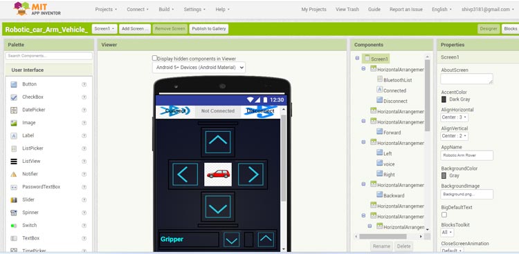
In Playstore there are a lot of different app’s for controlling a robotic arm. But for this project I am creating my own Android app with the help of MIT App Inventor.
You can download the App .apk file for Bluetooth:
To connect the Bluetooth-controlled robotic arm Car with your phone, follow these steps:
Open the "Robotic Arm Car" app on your Android device. Please note that currently, this app is not available for iOS users.
Turn on Bluetooth on your phone by going to your phone's settings.
Connect your phone to the HC-05 Bluetooth module. If you have a new HC-05 module, there is an additional step before connecting.
Go to the Bluetooth settings on your phone.
Search for Bluetooth devices.
You will find a Bluetooth device named HC-05.
Pair the Bluetooth device with your phone by selecting it.
During the pairing process, you will be prompted to enter a password.
The default password for HC-05 is usually either 1234 or 0000.
Enter the password and proceed with the pairing process.
Once the pairing is successful, your Bluetooth-controlled robotic arm Car is now connected to your Android device.
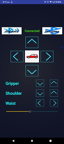
This app features a total of 10 control buttons, designed to facilitate seamless interaction. Four of these buttons are dedicated to directing the robot's movements—forward, backwards, right, and left. The remaining six buttons are specifically allocated for fine-tuning the angles of the robotic arm servos.
Once the HC-05 Bluetooth module is properly paired with an Android phone using our dedicated app, the user can effortlessly activate these control buttons. Upon pressing a control key, the Android phone promptly sends and receives the corresponding value, ensuring precise and responsive control over the robot and its robotic arm.
Conclusion
Modelling an Arm robot manipulator is complicated work, starting from how it moves in kinematics and how much energy is needed in dynamics. Building a Bluetooth-controlled robotic arm with Arduino provides a hands-on introduction to robotics and automation. This project presents the design of a 2-DOF manipulator robot prototype for the application of lifting and moving light material objects with the help of a Gripper. By combining servos, a motor driver, and Bluetooth communication, enthusiasts can create a versatile and interactive mechanical system. This project not only demonstrates the fusion of hardware and software but also serves as a stepping stone to more complex robotic endeavors. Whether you're an aspiring engineer or simply curious about robotics, this project offers an exciting and educational journey into the world of automation.
We have built a variety of electronics projects that offer clear guidance, well-designed circuits, and real-life practical uses.
Complete Project Code
Code #1
#include     // include servo library
// Define 3 Servos
Servo myServo1; // waist or base Servo
Servo myServo2; // shoulder Servo
Servo myServo3; // gripper Servo
void setup() {
 // Attach servos to Arduino PWM Pins
  myServo1.attach(5);
  myServo2.attach(6);
  myServo3.attach(3);
  myServo1.write(90);
  myServo2.write(90);
  myServo3.write(90);
}
 void loop() {
}

Code #2
#include <Servo.h>

Servo motor_1;
Servo motor_2;
Servo motor_3;

//#define enA 9  //Enable1 L298 Pin enA
#define in1 7 //Motor1  L298 Pin in1
#define in2 8 //Motor1  L298 Pin in1
#define in3 12 //Motor2  L298 Pin in1
#define in4 11 //Motor2  L298 Pin in1
//#define enB 9  //Enable2 L298 Pin enB

int servo1 = 90;
int servo2 = 0;
int servo3 = 90;

int bt_data;
int Speed = 130;

void setup(){

Serial.begin(9600); // initialize serial communication at 9600 bits per second:

motor_1.attach(5);   // Waist Servo
motor_2.attach(6);   // Shoulder Servo
motor_3.attach(3);   // Gripper Servo

motor_1.write(servo1);
motor_2.write(servo2);
motor_3.write(servo3);

//pinMode(enA, OUTPUT); // declare as output for L298 Pin enA
pinMode(in1, OUTPUT); // declare as output for L298 Pin in1
pinMode(in2, OUTPUT); // declare as output for L298 Pin in2
pinMode(in3, OUTPUT); // declare as output for L298 Pin in3
pinMode(in4, OUTPUT); // declare as output for L298 Pin in4
//pinMode(enB, OUTPUT); // declare as output for L298 Pin enB

digitalWrite(in1, LOW); //Right Motor forword Pin
digitalWrite(in2, LOW); //Right Motor backword Pin
digitalWrite(in3, LOW); //Left Motor backword Pin
digitalWrite(in4, LOW); //Left Motor forword Pin

delay(1000);
}

void loop(){
//if some date is sent, reads it and saves in state

if(Serial.available() > 0){
bt_data = Serial.read();
Serial.println(bt_data);
if(bt_data > 20)
{Speed = bt_data;}
}

//analogWrite(enA, Speed); // Write The Duty Cycle 0 to 255 Enable Pin A for Motor1 Speed
//analogWrite(enB, Speed); // Write The Duty Cycle 0 to 255 Enable Pin B for Motor2 Speed


if(bt_data == 1)
  {forword(); }  // if the bt_data is '1' the DC motor will go forward
else if(bt_data == 2)
  {backword();}  // if the bt_data is '2' the motor will Reverse
else if(bt_data == 3)
  {turnLeft();}  // if the bt_data is '3' the motor will turn left
else if(bt_data == 4)
  {turnRight();} // if the bt_data is '4' the motor will turn right
else if(bt_data == 5)
  {Stop(); }     // if the bt_data '5' the motor will Stop


else if (bt_data == 8){
if(servo1<180){servo1 = servo1+1;}
motor_1.write(servo1);
}
else if (bt_data == 9){
if(servo1>0){servo1 = servo1-1;}
motor_1.write(servo1);
}

else if (bt_data == 10){
if(servo2>0){servo2 = servo2-1;}
motor_2.write(servo2);
}
else if (bt_data == 11){
if(servo2<180){servo2 = servo2+1;}
motor_2.write(servo2);
}

else if (bt_data == 16){
if(servo3>60){servo3 = servo3-1;}
motor_3.write(servo3);
}
else if (bt_data == 17){
if(servo3<150){servo3 = servo3+1;}
motor_3.write(servo3);
}

delay(30);
}


void forword(){  //forword
digitalWrite(in1, HIGH);   //Right Motor forword Pin
digitalWrite(in2, LOW);   //Right Motor backword Pin
digitalWrite(in3, HIGH);  //Left Motor forward Pin
digitalWrite(in4, LOW);   //Left Motor backward Pin
}

void backword(){ //backword
digitalWrite(in1, LOW);
digitalWrite(in2, HIGH);
digitalWrite(in3, LOW);
digitalWrite(in4, HIGH);
}

void turnRight(){ //turnRight
digitalWrite(in1, LOW);
digitalWrite(in2, HIGH);
digitalWrite(in3, HIGH);
digitalWrite(in4, LOW);
}

void turnLeft(){ //turnLeft
digitalWrite(in1, HIGH);
digitalWrite(in2, LOW);
digitalWrite(in3, LOW);
digitalWrite(in4, HIGH);
}

void Stop(){ //stop
digitalWrite(in1, LOW);
digitalWrite(in2, LOW);
digitalWrite(in3, LOW);
digitalWrite(in4, LOW);
}Comments
Hola amigos, gran trabajo. Estoy armando un brazo robotico de 4 servomotres mg995, para cintura, hombro, codo y pinzas. Busco algo justo asi, ya que tengo un tanque y un carro arduino de 6 motores y queria unirlos. Mi pregunta es sobre el codigo, si me podian facilitar un codigo pero para controlar 4 servomotores. Muchas gracias
You can use the same code, just define an additional servo and modify the app accordingly.
Do you hav ethe file for the car's base?

Hi, Can you share the MIT App Inventor FIle to create app for more servo motors