

Analog to digital conversion is a very important task in embedded electronics, as most of the sensors provide output as analog values and to feed them into microcontroller which only understand binary values, we have to convert them into Digital values. So to be able to process the analog data, microcontrollers need Analog to Digital Converter.
Some microcontroller has inbuilt ADC like Arduino, MSP430, PIC16F877A but some microcontroller don’t have it like 8051, Raspberry Pi etc and we have to use some external Analog to digital converter ICs like ADC0804, ADC0808. Below you can find various examples of ADC with different microcontrollers:
- How to Use ADC in Arduino Uno?
- Raspberry Pi ADC Tutorial
- Interfacing ADC0808 with 8051 Microcontroller
- 0-25V Digital Voltmeter using AVR Microcontroller
- How to use ADC in STM32F103C8
- How to use ADC in MSP430G2
- How to use ADC in ARM7 LPC2148
- Using ADC Module of PIC Microcontroller with MPLAB and XC8
In this tutorial, we are going to check how to interface PCF8591 ADC/DAC module with Arduino.
We also covered Arduino DAC Tutorial, where we interfaced MCP4725 DAC Module with Arduino.
Required Components
- Arduino UNO
- PCF8591 ADC Module
- 100K Pot
- Jumper Cables
PCF8591 ADC/DAC Module
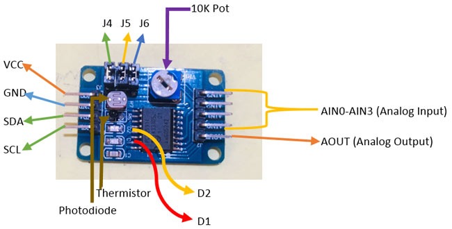
PCF8591 is an 8 bit analog to digital or 8 bit digital to analog converter module meaning each pin can read analog values up to 256. It also has LDR and thermistor circuit provided on the board. This module has four analog input and one analog output. It works on I2C communication, so there are SCL and SDA pins for serial clock and serial data address. It requires 2.5-6V supply voltage and have low stand-by current. We can also manipulate the input voltage by adjusting the knob of potentiometer on the module. There are also three jumpers on the board. J4 is connected to select the thermistor access circuit, J5 is connected to select the LDR/photo resistor access circuit and J6 is connected to select the adjustable voltage access circuit. To access these circuits you have to use the addresses of these jumpers: 0x50 for J6, 0x60 for J5 and 0x70 for J4. There are two LEDs on board D1 and D2- D1 shows the output voltage intensity and D2 shows the intensity of supply voltage. Higher the output or supply voltage, higher the intensity of LED D1 or D2. You can also test these LEDs by using a potentiometer on VCC or on AOUT pin.
Interfacing PCF8591 ADC/DAC Module with Arduino
Interfacing of PCF8591 with Arduino is very easy. In this interfacing example, we will read the analog values from any of the analog pins and change those values by a 100K pot. Firstly, connect VCC and GND to 5V and GND of Arduino. Next, connect the SDA and SCL to A4 and A5 of Arduino. Now, connect a 100K pot with AIN0 as shown in figure. For LCD, data pins (D4-D7) are connected to digital pins D5-D2 of Arduino and RS and EN pins are connected to D12 and D11 of Arduino. V0 of LCD is connected to pot and a 100k pot, which is used to control the brightness of LCD.


Programming for Arduino PCF8591 Analog to Digital Conversion (ADC)
The complete program and working video is given at the end of this tutorial.
Firstly, we need to define the library for I2C communication and LCD display.
#include<Wire.h>
#include <LiquidCrystal.h>
Then define some macros. The first macro is for defining the address of data bus for IC and second macro is for defining the address of first input pin of module, where the input from pot is given.
#define PCF8591 (0x90 >> 1)
#define AIn0 0x00
Next define the pin connections of LCD with Arduino and initialize the value which we are getting at analog pin.
const int rs = 12, en = 11, d4 = 5, d5 = 4, d6 = 3, d7 = 2;
LiquidCrystal lcd(rs, en, d4, d5, d6, d7);
int Value = 0;
Now, let’s come to setup function. Here, in first line we’ve initialized the I2C communication. And in the second line, we’ve initialized the LCD display on which we are printing the analog values. Learn more about interfacing 16x2 LCD with Arduino here.
void setup()
{
 Wire.begin();
 lcd.begin(16,2);
}
In loop function, the first line is to begin the transmission, i.e. it starts the PCF8591. The second line tells the IC to make the analog measurement at the first analog input pin. Third line ends the transmission and fourth line gets the measured data from analog pin.
void loop()
{
 Wire.beginTransmission(PCF8591);
 Wire.write(AIn0);
 Wire.endTransmission();
 Wire.requestFrom(PCF8591, 1);
In next portion, put the value read from analog pin to Value variable defined earlier. And in next lines, print that value to the LCD.
 Value=Wire.read();
 lcd.print("ADC Value=");
 lcd.print(Value);
 delay(500);
 lcd.clear();}
Finally upload the code in Arduino and run it. The analog values will start showing up on LCD display. Adjust the pot’s knob, and you will see the gradual change in the values.
 with Arduino")
Complete Project Code
#include <LiquidCrystal.h>

#include<Wire.h>

#define PCF8591 (0x90 >> 1)

#define AIN0 0x00

const int rs = 12, en = 11, d4 = 5, d5 = 4, d6 = 3, d7 = 2;

LiquidCrystal lcd(rs, en, d4, d5, d6, d7);

int Value = 0;
void setup()

{

  Wire.begin();

  lcd.begin(16,2);

}

void loop()

{

  Wire.beginTransmission(PCF8591);

  Wire.write(AIN0);

  Wire.endTransmission();

  Wire.requestFrom(PCF8591, 1);
  Value = Wire.read();

  lcd.print("ADC Value=");

  lcd.print(Value);

  delay(500);

  lcd.clear();

}
