
We all know that the Microcontrollers work only with digital values but in real world we have to deal with analog signals. That’s why ADC (Analog to Digital Converters) is there to convert real world Analog values into Digital form so that microcontrollers can process the signals. But what if we need Analog signals from digital values, so here comes the DAC (Digital to Analog Converter).
A simple example for Digital to Analog converter is recording a song in studio where an artist singer is using microphone and singing a song. These analog sound waves are converted into digital form and then stored in a digital format file and when the song is played using the stored digital file those digital values are converted into analog signals for speaker output. So in this system DAC is used.
DAC can be used in many applications such as Motor control, Control Brightness of the LED Lights, Audio Amplifier, Video Encoders, Data Acquisition Systems etc.
In many microcontrollers there is an internal DAC that can be used to produce analog output. But Arduino processors such as ATmega328/ATmega168 don’t have DAC inbuilt. Arduino has ADC feature (Analog to Digital Converter) but it has no DAC (Digital to Analog Converter). It has a 10-bit DAC in internal ADC but this DAC cannot be used as standalone. So here in this Arduino DAC tutorial, we use an additional board called MCP4725 DAC Module with Arduino.
MCP4725 DAC Module (Digital to Analog Converter)
MCP4725 IC is a 12-Bit Digital to Analog Converter Module which is used to generate output analog voltages from (0 to 5V) and it is controlled by using I2C communication. It also comes with on board nonvolatile memory EEPROM.
This IC has 12-Bit resolution. This means we use (0 to 4096) as input to provide the voltage output with respect to reference voltage. Maximum reference voltage is 5V.
Formula to calculate Output Voltage
O/P Voltage = (Reference Voltage / Resolution) x Digital Value
For Example if we use 5V as reference voltage and let’s assume that digital value is 2048. So to calculate the DAC output.
O/P Voltage = (5/ 4096) x 2048 = 2.5V
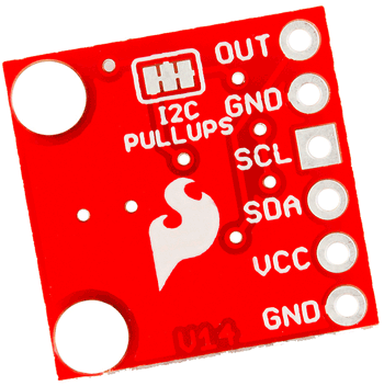
Pinout of MCP4725
Below is the image of MCP4725 with clearly indicating pin names.
|
Pins of MCP4725 |
Use |
|
OUT |
Outputs Analog Voltage |
|
GND |
GND for Output |
|
SCL |
I2C Serial Clock line |
|
SDA |
I2C Serial Data line |
|
VCC |
Input Reference Voltage 5V or 3.3V |
|
GND |
GND for input |
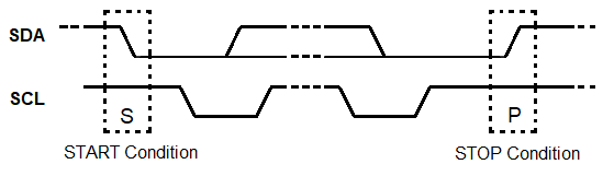
I2C Communication in MCP4725 DAC
This DAC IC can be interfaced with any microcontroller using the I2C communication. I2C communication requires only two wires SCL and SDA. By default, the I2C address for MCP4725 is 0x60 or 0x61 or 0x62. For me its 0x61. Using I2C bus we can connect multiple MCP4725 DAC IC. Only thing is we need to change the I2C address of the IC. I2C communication in Arduino is already explained in detail in previous tutorial.
In this tutorial we will connect a MCP4725 DAC IC with Arduino Uno and provide analog input value to Arduino pin A0 by using a potentiometer. Then ADC will be used to convert analog value into digital form. After that those digital values are sent to MCP4725 via I2C bus to be converted into analog signals using the DAC MCP4725 IC. Arduino pin A1 is used to check the analog output of MCP4725 from the pin OUT and finally display the both ADC & DAC values and voltages in the 16x2 LCD display.
Components Required
- Arduino Nano / Arduino Uno
- 16x2 LCD display module
- MCP4725 DAC IC
- 10k Potentiometer
- Breadboard
- Jumper Wires
Circuit Diagram

Below table shows the connection between MCP4725 DAC IC, Arduino Nano and Multi-meter
|
MCP4725 |
Arduino Nano |
Multimeter |
|
SDA |
A4 |
NC |
|
SCL |
A5 |
NC |
|
A0 or OUT |
A1 |
+ve terminal |
|
GND |
GND |
-ve terminal |
|
VCC |
5V |
NC |
Connection between 16x2 LCD and Arduino Nano
|
LCD 16x2 |
Arduino Nano |
|
VSS |
GND |
|
VDD |
+5V |
|
V0 |
From Potentiometer Centre Pin to adjust contrast of LCD |
|
RS |
D2 |
|
RW |
GND |
|
E |
D3 |
|
D4 |
D4 |
|
D5 |
D5 |
|
D6 |
D6 |
|
D7 |
D7 |
|
A |
+5V |
|
K |
GND |
A potentiometer is used with center pin connected to A0 analog input of Arduino Nano, Left pin connected to GND and right most pin connected to 5V of Arduino.
DAC Arduino Programming
Complete Arduino code for DAC tutorial is given at the end with a demonstration video. Here we have explained the code line by line.
First, include the library for I2C and LCD using wire.h and liquidcrystal.h library.
#include<Wire.h>
#include <LiquidCrystal.h>
Next define and initialize the LCD pins according to pins we have connected with the Arduino Nano
LiquidCrystal lcd(2,3,4,5,6,7); //Define LCD display pins RS,E,D4,D5,D6,D7
Next define the I2C address of the MCP4725 DAC IC
#define MCP4725 0x61
In the void setup()
First begin the I2C communication at the pins A4 (SDA) and A5 (SCL) of Arduino Nano
Wire.begin(); //Begins the I2C communication
Next set the LCD display in the 16x2 mode and display a welcome message.
lcd.begin(16,2); //Sets LCD in 16X2 Mode
lcd.print("CIRCUIT DIGEST");
delay(1000);
lcd.clear();
lcd.setCursor(0,0);
lcd.print("Arduino");
lcd.setCursor(0,1);
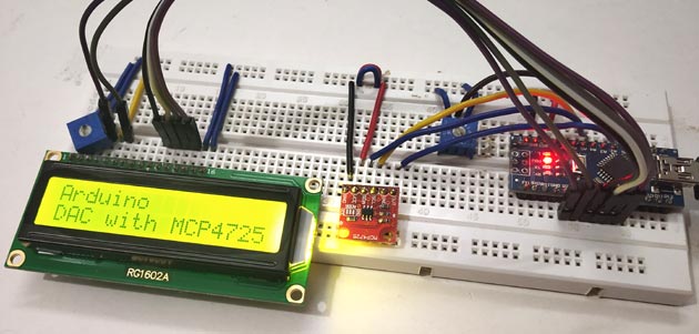
lcd.print("DAC with MCP4725");
delay(2000);
lcd.clear();
In the void loop()
1. First in buffer[0] put the control byte value (0b01000000)
(010-Sets MCP4725 in Write mode)
buffer[0] = 0b01000000;
2. The following statement reads the analog value from pin A0 and converts it into digital values (0-1023). Arduino ADC is 10-bit resolution so multiply it with 4 gives: 0-4096, as the DAC is 12-bit resolution.
adc = analogRead(A0) * 4;
3. This statement is to find the voltage from the ADC input value (0 to 4096) and the reference voltage as 5V
float ipvolt = (5.0/4096.0)* adc;
4. Below first line puts the Most significant bit values in buffer[1] by shifting 4 bits to right in ADC variable, and second line puts the least significant bit values in buffer[2] by shifting 4 bits to left in ADC variable.
buffer[1] = adc >> 4;
buffer[2] = adc << 4;
5. The following statement reads analog voltage from A1 that is the DAC output (MCP4725 DAC IC’s OUTPUT pin). This pin can also be connected to multimeter to check the output voltage. Learn how to use Multimeter here.
unsigned int analogread = analogRead(A1)*4 ;
6. Further the voltage value from the variable analogread is calculated using the formula below
float opvolt = (5.0/4096.0)* analogread;
7. Following statement is used to begins the transmission with MCP4725
Wire.beginTransmission(MCP4725);
Sends the control byte to I2C
Wire.write(buffer[0]);
Sends the MSB to I2C
Wire.write(buffer[1]);
Sends the LSB to I2C
Wire.write(buffer[2]);
Ends the transmission
Wire.endTransmission();
Now finally display those results in the LCD 16x2 display using lcd.print()
 lcd.setCursor(0,0);
 lcd.print("A IP:");
  lcd.print(adc);
  lcd.setCursor(10,0);
  lcd.print("V:");
  lcd.print(ipvolt);
  lcd.setCursor(0,1);
  lcd.print("D OP:");
  lcd.print(analogread);
  lcd.setCursor(10,1);
  lcd.print("V:");
  lcd.print(opvolt);
  delay(500);
  lcd.clear();
Digital to Analog Conversion using MCP4725 and Arduino
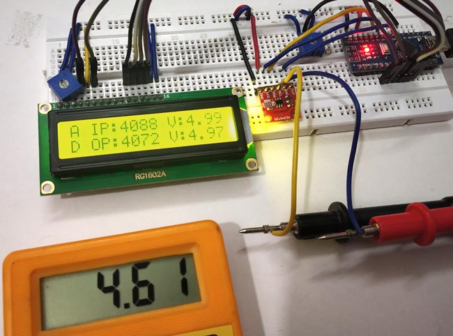
After completing all the circuit connections and upload the code into Arduino, vary the potentiometer and watch the output on LCD. First line of LCD will show the input ADC value and voltage, and second line will show the output DAC value and voltage.

You can also check the output voltage by connecting a multimeter to the OUT and GND pin of MCP4725.
This is how we can convert Digital values into Analog by interfacing DAC module MCP4725 with Arduino.
Complete Project Code
#include<Wire.h>                   //Include Wire library for using I2C functions

#include <LiquidCrystal.h>         //Include LCD library for using LCD display functions
#define MCP4725 0x61              //MCP4725 address as 0x61 Change yours accordingly

LiquidCrystal lcd(2,3,4,5,6,7);   //Define LCD display pins RS,E,D4,D5,D6,D7


unsigned int adc;

byte buffer[3];
void setup()

{

  Wire.begin();                    //Begins the I2C communication

  lcd.begin(16,2);                 //Sets LCD in 16X2 Mode

  lcd.print("CIRCUIT DIGEST");

  delay(1000);

  lcd.clear();

  lcd.setCursor(0,0);

  lcd.print("Arduino");

  lcd.setCursor(0,1);

  lcd.print("DAC with MCP4725");

  delay(2000);

  lcd.clear();


}
void loop()
{

  buffer[0] = 0b01000000;            //Sets the buffer0 with control byte (010-Sets in Write mode)

  adc = analogRead(A0) * 4;          //Read Analog value from pin A0 and convert into digital (0-1023) multiply with 4 gives (0-4096)


  float ipvolt = (5.0/4096.0)* adc;  //Finding voltage formula (A0)

  buffer[1] = adc >> 4;              //Puts the most significant bit values

  buffer[2] = adc << 4;              //Puts the Least significant bit values


  unsigned int analogread = analogRead(A1)*4 ; //Reads analog voltage from A1


  float opvolt = (5.0/4096.0)* analogread; //Finding Voltage Formula (A1)


  Wire.beginTransmission(MCP4725);         //Joins I2C bus with MCP4725 with 0x61 address


  Wire.write(buffer[0]);            //Sends the control byte to I2C

  Wire.write(buffer[1]);            //Sends the MSB to I2C

  Wire.write(buffer[2]);            //Sends the LSB to I2C


  Wire.endTransmission();           //Ends the transmission
  lcd.setCursor(0,0);

  lcd.print("A IP:");

  lcd.print(adc);                   //Prints the ADC value from A0

  lcd.setCursor(10,0);

  lcd.print("V:");                  //Prints the Input Voltage at A0

  lcd.print(ipvolt);

  lcd.setCursor(0,1);

  lcd.print("D OP:");

  lcd.print(analogread);             //Prints the ADC value from A1 (From DAC)

  lcd.setCursor(10,1);

  lcd.print("V:");

  lcd.print(opvolt);                 //Prints the Input Voltage at A1 (From DAC)


  delay(500);

  lcd.clear();

}
