

Just like stethoscope for doctors, stack overflow for programmers, spanners for Mechanic and Jarvis for Tony Stark a Multimeter is a very essential instrument for engineers who are interested in working with electronics. Perhaps this would be the first instrument that we get introduced to when starting to explore things related to electronics.
In this article we will learn how to use a digital multimeter and how this will help us in our journey with electronics, this will be a very basic article which will take your through the different operations of a multimeter will illustrative pictures and videos. At the end of this article you will learn how to measure voltage with multimeter, measure DC current, check for continuity, measure resistance and also check if few components like LED and diodes are in working state. Pheww... sounds like a big list isn’t it! But trust me they will be very useful when you are trying out stuff on your own. Hence sit back and read through, while I will try making this article as intresting as possible.
How to Measure Voltage with Multimeter:
There are two different Voltages in general that can be measured by the Multimeter. One is DC voltage and the other being AC Voltage. All most all electronics devices work on DC voltage (Conventional AC will be converted to DC) and hence DC voltage is the most measured parameter.
Our Multimeter can measure both AC and DC voltages. Let us start with DC voltage.
How to Measure DC Voltage with Multimeter:
There are two things to check on a multimeter before proceeding with any measurement. They are the Position of Test Leads (a.k.a test probes) and selection of mode/range. By default the position of black test lead should be in the COM slot and the Red test lead should be in the V slot. This position will change only if we are measuring current.
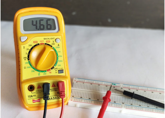
So, to measure a voltage the black test lead should be in COM slot and red lead should be in V slot. Now we have to select the Mode by using the regulator like knob in the centre of the multimeter. We should look for the DC voltage symbol (shown in picture below) and select a range under it. By default the range will be like 200mV, 2V, 20V, 200V and 600V. Based on the voltage level that you are planning to measure you can select the range. And don’t worry it is not going to blow up if you select a lesser range you can always hit and try. For example if you are measuring 35V and if you place it at 20V range then you meter will read simply read 1, this means that you should select a high voltage range in this case 200V. In the below picture I have set the meter to read DC Voltage that is within 20V range.
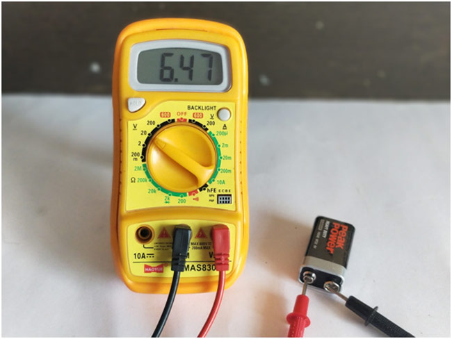
Once we have set the meter we can simply place the probes on the terminals on which we have to measure the voltage. Place the red lead on the positive terminal and Black Lead on the Negative terminal and you will get the value of Voltage. If you reverse the polarity of the cable you will still get the value but it will be with a negative sign, always use the probes in correct polarity to avoid errors. You can measure voltage of a battery, DC adapter, Phone charger and even the voltage drop across each component in a circuit while debugging applications. The below video shows you how to measure DC voltage with Multimeter.
How to Measure AC Voltage with Multimeter:
While AC voltage is rarely measured using Digital Multimeter it is still important at places where AC mains are involved. To measure AC voltage place the Red lead at V slot and Black lead at COM slot as shown in the picture below. Now set the mode by using the knob, we have to place it at AC voltage symbol (shown in picture below). Normally we will have two ranges for AC voltages, they are 200V and 600V. For measuring AC voltage in India which is 220V we have to place it in 600V mode as shown in the picture below.
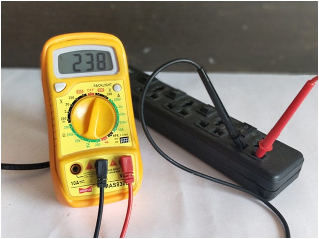
The measuring process is exactly similar to measuring DC voltage, but here we do not have any polarity since we are dealing with AC. The following video shows how to measure AC mains voltage using a Multimeter.
How to Measure DC Current with Multimeter:
Most of the conventional Multimeters will not have the option to measure AC current, hence we will discuss only about measuring DC current, however if you are looking for a instrument to measure current Clamp meter. Do not try measuring AC current with your DC multimeter it might damage the meter permanently.
To measure DC current the black Probe should be placed in COM slot and the red probe should be placed in the A slot as shown in the picture below. This is done because current should always be measured in series. Also note that some meters might have two A slot based on the range so make sure to read the symbol before connecting. Then we can select the mode by turning the knob to the dc current symbol (shown in picture). Again we have ranges from 200 micro amps to 10A we can select the required range. In the below image the meter is set to read DC current at 2mA.So I am using the same V slot. But if the current is 10A then I should have changed the slot.
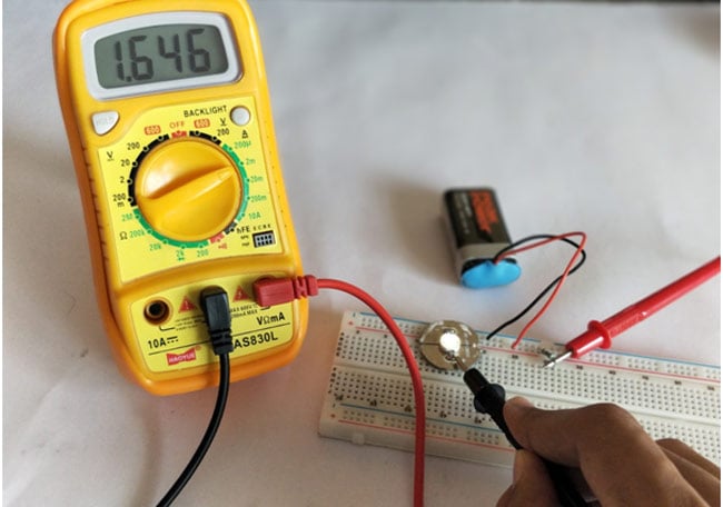
As said earlier, current can be measure only in series with the load. So if you want to measure the current drawn flowing through any wire, you have to disconnect the wire and place this meter in series by placing one probe at one end and the other at the other end. The below video shows how to measure the current flowing through a wire that is powering the LED.
How to Check Continuity with Multimeter:
Another important and useful feature of a multimeter is checking for continuity. This is a life saver tool that helps to debug electronics, be it your new PCB or a simple breadboard connection you can use continuity tool to check if there a connection between two terminals. This can also be used to detect broken wire.
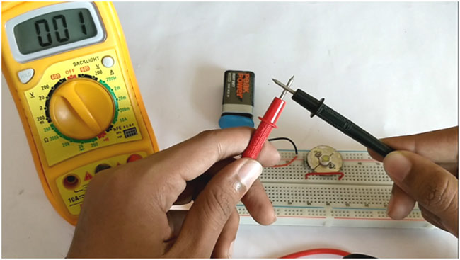
The check for continuity of any wire or circuit, place the Black probe on the COM slot and the Red probe on the V slot, then turn the knob to the continuity symbol (shown in picture below). To check continuity between terminals say terminal A and terminal B, place one probe (any probe) on terminal A and the other on Terminal B. If there is connection between terminal A and terminal B then the meter will read zero and you will also get a “beep” sound. If there is not connection you won’t get the beep sound.
The below video will show how to check for continuity in circuits and how to detect broken connections.
How to Measure Resistance with Multimeter:
One of the most use and unavoidable component in electronics are Resistors. There are a wide range of resistors available based on their power rating and resistance value, the value of each resistor will be mentioned with the help of colour codes. It is important to learn how to read a resistors value using colour code or at least keep an online resistor value calculator, but there might be certain cases it’s hard to read the colour. In those cases we can use a multimeter to read the resistance value of the resistor easily.
To measure resistance with multimeter make sure the black probe is on the COM slot and the red probe in on the V slot. Now, turn the knob to the Resistance symbol. Again we have ranges from 200Ω to 2MΩ, select the one that you desire, here in the below picture I am placing it on 20k value. You can always try different ranges to get the right range that suits for your resistor.
The below video shows how we can measure the resistance value using multimeter. The value measured will not be accurate; this can just be used as an approximation. Also if the resistor is placed inside a circuit then we should not measure the resistance using multimeter, since it will show wrong values.
How to Check Components using Diode Mode:
Another interesting mode in the multimeter is the Diode mode. Ever wondered if the LED/Diode in your circuit is in working condition, or what color your LED might glow when powered! Think no more get your multimeter place it in diode mode and check it in no time. You check the polarity of your LED and even make it glow to check for its working.
To use the diode mode, make sure your black probe is in the COM slot and the red probe is in the V slot. Now, adjust the regulator knob to the diode symbol as shown in the picture below. The diode mode and the 2K mode resistance mode use the same place so don’t worry about it. Now place the Red probe on the Anode and the Black probe on the cathode of the LED and it should make the LED glow. This works because LED is also a form of diode, if you reverse the polarity the LED will not glow the same can be used to check the working of a diode.
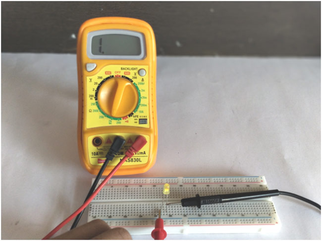
The below video shows how we can use the Diode mode to check for LED and diode’s working condition. Again this technique is not advisable to be used when the components are in a circuit, because the existing connections might cause a bad/wrong result.
Informative article sharing this article post. Honestly, this is the first time I read the blog article. But I really satisfied to read your blog article. I need a digital multimeter for my home working. But I am a little bit confused how can I test. But now am clear my all confusion. Thanks for your helpful sharing. Guys would love it.

it is very good.