
Making wireless projects in embedded electronics becomes very important and helpful as there are no jumbled wires all over which makes the device more handy and portable. There are various wireless technologies such as Bluetooth, WiFi, 433 MHz RF (Radio Frequency) etc. Every technology has its own advantages and disadvantages such as cost, distance or range transfer, speed or throughput etc. Today we will use RF module with STM32 to send and receive the data wirelessly. If you are new to STM32 Microcontroller then start with Blinking LED with STM32 using Arduino IDE and check all other STM32 projects here.
Apart from this, we have also used RF 433Mhz Wireless Module with other microcontrollers to build some wireless controlled projects, such as:
- RF Controlled Home Appliances
- RF Remote Controlled LEDs Using Raspberry Pi
- RF Controlled Robot
- Interfacing RF module with Arduino
- PIC to PIC Communication using RF Module
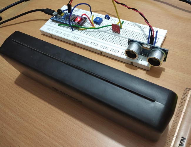
Here we will interface a 433MHz RF wireless module with STM32F103C8 microcontroller. The project is divided into two parts. The transmitter will be interfaced with STM32 and the receiver will be interfaced with Arduino UNO. There will be different circuit diagram and sketches for both transmitting as well receiving part.
In this tutorial, RF Transmitter sends two values to Receiver side: the distance measured using ultrasonic sensor and the potentiometer ADC value (0 to 4096) which is mapped as number from (0 to 100). The RF receiver of Arduino receives both the values and prints those distance and number values in 16x2 LCD display wirelessly.
Components Required
- STM32F103C8 Microcontroller
- Arduino UNO
- 433Mhz RF Transmitter & Receiver
- Ultrasonic Sensor (HC-SR04)
- 16x2 LCD display
- 10k Potentiometer
- Breadboard
- Connecting Wires
433Mhz RF Transmitter and Receiver Module)
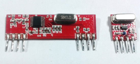
RF Transmitter Pinout:
|
433Mhz RF Transmitter |
Pin Description |
|
ANT |
For connecting Antenna |
|
GND |
GND |
|
VDD |
3.3 to 5V |
|
DATA |
Data to be transmitted to receiver is given here |
RF Receiver Pinout:
|
433Mhz RF Receiver |
USE |
|
ANT |
For connecting Antenna |
|
GND |
GND |
|
VDD |
3.3 to 5V |
|
DATA |
Data to be received from Transmitter |
|
CE/DO |
It is also a Data pin |
433 MHz Module Specifications:
- Receiver Operating Voltage: 3V to 5V
- Transmitter Operating Voltage: 3V to 5V
- Operating frequency: 433 MHz
- Transmission Distance: 3 meters (without antenna) to 100 meters (maximum)
- Modulating Technique: ASK (Amplitude shift keying)
- Data Transmission speed: 10Kbps
Circuit Diagram of RF Transmitter with STM32F103C8

Circuit Connections between RF Transmitter & STM32F103C8:
|
STM32F103C8 |
RF Transmitter |
|
5V |
VDD |
|
GND |
GND |
|
PA10 |
DATA |
|
NC |
ANT |
Circuit Connections between Ultrasonic Sensor & STM32F103C8:
|
STM32F103C8 |
Ultrasonic Sensor (HC-SR04) |
|
5V |
VCC |
|
PB1 |
Trig |
|
PB0 |
Echo |
|
GND |
GND |
A 10k potentiometer is connected with the STM32F103C8 to provide input Analog value (0 to 3.3V) to the ADC pin PA0 of STM32.
Circuit Diagram of RF Receiver with Arduino Uno
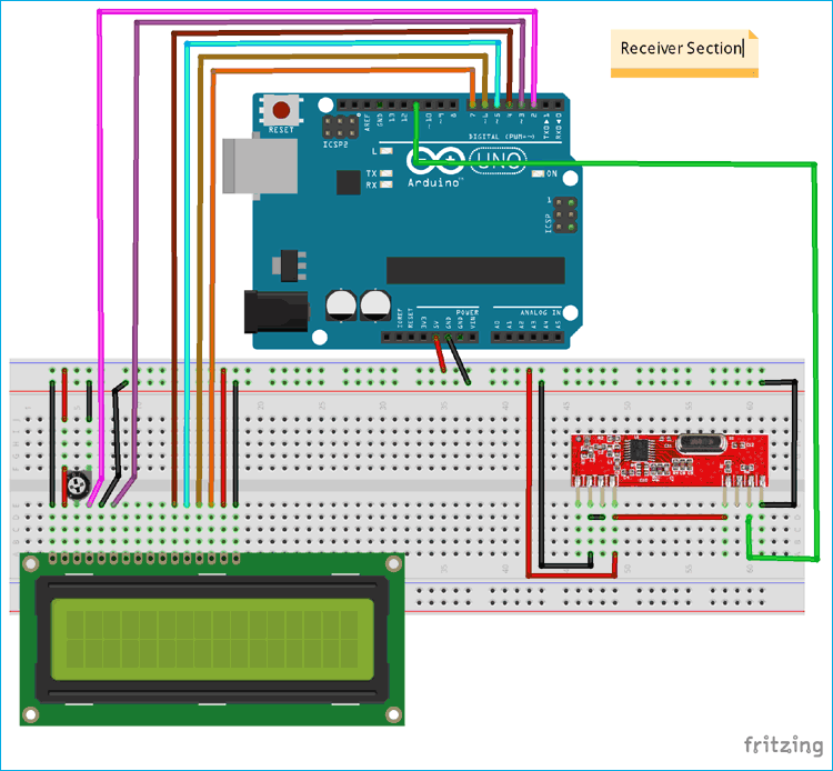
Circuit Connections between RF Receiver & Arduino UNO:
|
Arduino UNO |
RF Receiver |
|
5V |
VDD |
|
GND |
GND |
|
11 |
DATA |
|
NC |
ANT |
Circuit Connections between 16x2 LCD & Arduino UNO:
|
LCD Pin Name |
Arduino UNO Pin Name |
|
Ground (Gnd) |
Ground (G) |
|
VCC |
5V |
|
VEE |
Pin from Centre of Potentiometer for Contrast |
|
Register Select (RS) |
2 |
|
Read/Write (RW) |
Ground (G) |
|
Enable (EN) |
3 |
|
Data Bit 4 (DB4) |
4 |
|
Data Bit 5 (DB5) |
5 |
|
Data Bit 6 (DB6) |
6 |
|
Data Bit 7 (DB7) |
7 |
|
LED Positive |
5V |
|
LED Negative |
Ground (G) |
The coding will be explained in brief below. There will be two parts of the sketch where first part will be transmitter section and another will be receiver section. All sketch files and working video will be given at the end of this tutorial. To learn more about interfacing RF module with Arduino Uno, follow the link.
Programming STM32F103C8 for wireless RF Transmission
STM32F103C8 can be programmed using Arduino IDE. A FTDI programmer or ST-Link is not needed to upload the code to STM32F103C8. Simply connect to PC via USB port of STM32 and start programming with ARDUINO IDE. You can learn Programming your STM32 in Arduino IDE by following the link.
In the transmitter section the distance of the object in ‘cm’ is measured using ultrasonic sensor and the number value from (0 to 100) set using potentiometer which is transmitted via RF transmitter interfaced with STM32.
First the Radiohead library is included, it can be downloaded from here. As this library uses the ASK (Amplitude Shift Keying Technique) to transmit and receive data. This makes the programming very easy. You can include library in sketch by going into Sketch->include library->Add .zip library.
#include <RH_ASK.h>
As in this tutorial in the transmitter side an ultrasonic sensor is used to measure the distance so the trigger and echo pins are defined.
#define trigPin PB1
#define echoPin PB0
Next the object name for the RH_ASK library is set as rf_driver with the parameters such as speed (2000), RX pin (PA9) and TX pin (PA10).
RH_ASK rf_driver(2000, PA9, PA10);
Next the Strings variable needed in this program are declared.
String transmit_number;
String transmit_distance;
String transmit;
Next in the void setup(), the object for RH_ASK rf_driver is initialized.
rf_driver.init();
After that the trigger pin is set as OUTPUT pin and the PA0 (connected to potentiometer) and echo pin is set as INPUT pin. Serial communication is begin at baud rate of 9600.
   Serial.begin(9600);
    pinMode(PA0,INPUT);
    pinMode(echoPin,INPUT);
    pinMode(trigPin,OUTPUT);
Next in the void loop(), frst the potentiometer value that is the input Analog voltage is converted into digital value (ADC value is found). As the ADC of STM32 has 12-bit resolution. So, the digital value varies from (0 to 4096) which is mapped into (0 to 100).
    int analoginput = analogRead(PA0);
    int pwmvalue = map(analoginput,0,4095,0,100);
Next the distance is measured using ultrasonic sensor by setting the trigger high and low with a delay of 2 microseconds.
    digitalWrite(trigPin, LOW);
    delayMicroseconds(2);
    digitalWrite(trigPin, HIGH);
    delayMicroseconds(10);
    digitalWrite(trigPin, LOW);
The echo pin senses the reflected wave back, that is the time duration that triggered wave is reflected back is used in calculating the distance of object using the formula. Learn more how ultrasonic sensor calculates distance, by following the link.
    long duration = pulseIn(echoPin, HIGH);
    float distance= duration*0.034/2;
Now both the data number and distance measured is converted into string data and stored in respective string variables.
    transmit_number= String(pwmvalue);
    transmit_distance = String(distance);
Both the string is added as one line and stored in string called transmit and comma “,” is used to separate two strings.
transmit = transmit_pwm + "," + transmit_distance;
The transmit string is converted into character array.
const char *msg = transmit.c_str();
The data is transmitted and wait till it is sent.
    rf_driver.send((uint8_t *)msg, strlen(msg));
    rf_driver.waitPacketSent();
The string data sent is also displayed in the Serial Monitor.
Serial.println(msg);

Programming Arduino UNO as RF Receiver
Arduino UNO is programmed using the Arduino IDE. In the receiver section the data that is transmitted from the transmitter section and received by the RF receiver module and the string data received is split into respective data (distance and number) and displayed in the 16x2 LCD display.
Let’s see the receiver coding in brief:
Like in the transmitter section first the RadiohHead library is included. As this library uses the ASK (Amplitude Shift Keying Technique) to transmit and receive data. This makes the programming very easy.
#include <RH_ASK.h>
As LCD display is used here so the liquidcrystal library is also included.
#include <LiquidCrystal.h>
And the 16x2 LCD display pins connected with Arduino UNO are specified and declared using lcd as object.
LiquidCrystal lcd(2,3,4,5,6,7);
Next the String data variables to store string data are declared.
String str_receive;
String str_number;
String str_distance;
The object for the Radiohead library is declared.
RH_ASK rf;
Now in the void setup(), The LCD display is set in 16x2 mode and a welcome message is displayed and cleared.
    lcd.begin(16,2);
    lcd.print("CIRCUIT DIGEST");
    lcd.setCursor(0,1);
    lcd.print("RF with STM32");
    delay(5000);
    lcd.clear();
After that, the rf object is initialized.
rf.init();
Now in the void loop(), the Array buf[] is declared with size as 7. As the data sent from transmitter has 7 including the “,”. So, change this according to the data that is to be transmitted.
    uint8_t buf[7];
    uint8_t buflen = sizeof(buf);
If the string is available at the rf receiver module the if function checks the size and it executes. The rf.recv() is used to receive data.
if (rf.recv(buf, &buflen))
The buf has the received string so then received string is stored in a str_receive string variable.
str_receive = String((char*)buf);
This for loop is used to split the received string into two if it detects the ‘,’ in-between two strings.
      for (int i = 0; i < str_receive.length(); i++)
      {
      if (str_receive.substring(i, i+1) == ",")
      {
      str_number = str_receive.substring(0, i);
      str_distance = str_receive.substring(i+1);
      break;
      }
Two char arrays for two values are declared and the String that is split into two is stored in respected array by converting string into character array.
      char numberstring[4];
      char distancestring[3];
      str_distance.toCharArray(distancestring,3);
      str_number.toCharArray(numberstring,3);
After that convert the character array into integer using atoi()
      int distance = atoi(distancestring);
      int number = atoi(numberstring);
After converting into integer values the values distance and number is displayed in 16x2 LCD display
      lcd.setCursor(0,0);
      lcd.print("Number:");
      lcd.print(number);
      lcd.setCursor(0,1);
      lcd.print("Distance :");
      lcd.print(distance);
      lcd.print(" cm");
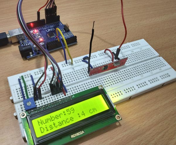
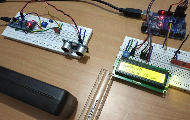
After uploading both the codes i.e. transmitter and receiver in the STM32 and Arduino UNO respectively, the data such as number and object distance measured using the STM32 is transmitted to the RF receiver via RF Transmitter and the values received are displayed in the LCD display wirelessly.
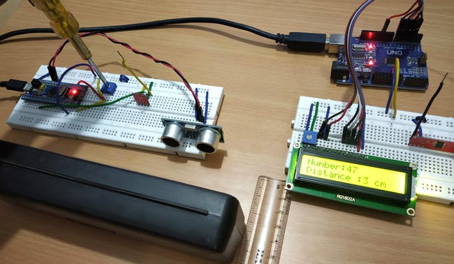
Testing STM 32 based RF Transmitter and Receiver
1. When number at 0 and the distance of object is at 6cm.
2. When number 47 and distance of object is at 3cm.
Complete Project Code
Transmitter code (STM32F103C8):
//433MHZ RF Trasmitter with STM32F103C8
//Transmitter Code
//Circuit Digest
#include <RH_ASK.h>                             //RadioHead library
#define trigPin PB1                             //Sets the Trigpin of Ultrasonic sensor as PB1
#define echoPin PB0                             //Sets the echoPin of Ultrasonic sensor as PB0
RH_ASK rf_driver(2000, PA9, PA10);              //Sets Pin PA9 as receiver and PA10 as transmitterand 2000 as Speed

String transmit_pwm;                            //Strings to store string value
String transmit_distance;
String transmit;
void setup()
{
    // Initialize ASK Object
    rf_driver.init();
    Serial.begin(9600);
    pinMode(PA0,INPUT);
    pinMode(echoPin,INPUT);
    pinMode(trigPin,OUTPUT);
}

void loop()
{
    int analoginput = analogRead(PA0);                    // ADC value from pin PA0 connected to Potentiometer
    int pwmvalue = map(analoginput,0,4096,0,100);         // Converts 0 to 4096 into 0 to 100

    digitalWrite(trigPin, LOW);                           //Makes TrigPin of Ultrasonic LOW
    delayMicroseconds(2);
    digitalWrite(trigPin, HIGH);                          //Makes TrigPin of Ultrasonic HIGH
    delayMicroseconds(10);
    digitalWrite(trigPin, LOW);                           //Makes TrigPin of Ultrasonic LOW
    long duration = pulseIn(echoPin, HIGH);               //Receives the Echo signal reflected
    float distance= duration*0.034/2;                     //Calculates distance in CM of object
    transmit_pwm = String(pwmvalue);                      //Convert value into string
    transmit_distance = String(distance);                 //Convert value into string
    transmit = transmit_pwm + "," + transmit_distance;    //Adds two String in one line
    const char *msg = transmit.c_str();                   //
    rf_driver.send((uint8_t *)msg, strlen(msg));          //Sends the String
    rf_driver.waitPacketSent();
    Serial.println(msg);                                  //Serial Print value for debug
    delay(1000);
}

Receiver Code (Arduino UNO):
//Receiver Arduino Code
//433MHZ RF with STM32F103C8 as Transmitter
//Circuit Digest

#include <RH_ASK.h>                 //Includes RadioHead Library
#include <LiquidCrystal.h>          //Includes the LCD display Library

LiquidCrystal lcd(2,3,4,5,6,7);     //Initialize lcd with Pins connected to Arduino
String str_receive;                 //Strings to Store Value
String str_number;
String str_distance;

RH_ASK rf;                          //rf as object for RG_ASK
void setup()
{
    lcd.begin(16,2);               //Lcd set as 16x2 Mode
    lcd.print("CIRCUIT DIGEST");   //Display Welcome message
    lcd.setCursor(0,1);
    lcd.print("RF with STM32");
    delay(5000);
    lcd.clear();
    rf.init();                     //Initialize rf Object
}

void loop()
{
    uint8_t buf[7];
    uint8_t buflen = sizeof(buf);
    if (rf.recv(buf, &buflen))
    {
      str_receive = String((char*)buf);                          // Receive String from the Transmitter
      for (int i = 0; i < str_receive.length(); i++)             // Split string into two string
      {
      if (str_receive.substring(i, i+1) == ",")
      {
      str_number = str_receive.substring(0, i);
      str_distance = str_receive.substring(i+1);
      break;
      }
    }
      char numberstring[4];
      char distancestring[3];

      str_distance.toCharArray(distancestring,3);              //Convert String into Char Array
      str_number.toCharArray(numberstring,3);

      int distance = atoi(distancestring);                    //Convery Array into integer value
      int number = atoi(numberstring);

      lcd.setCursor(0,0);
      lcd.print("Number:");
      lcd.print(number);                                     //Display number value at LCD display
      lcd.setCursor(0,1);
      lcd.print("Distance :");
      lcd.print(distance);                                   //Display distance value at LCD display
      lcd.print(" cm");
      delay(1500);
      lcd.clear();
}
}

Hi i like how your code works but now i would like to ask how would i do the conversions for only the Distance, i'm not sure how to modify this part of the Transmitter code. If you could please assist me thank you.
transmit = transmit_pwm + "," + transmit_distance; //Adds two String in one line
const char *msg = transmit.c_str();
///////////////// And this part of the Receiver code.
str_receive = String((char*)buf); // Receive String from the Transmitter
for (int i = 0; i < str_receive.length(); i++) // Split string into two string
{
if (str_receive.substring(i, i+1) == ",")
{
str_number = str_receive.substring(0, i);
str_distance = str_receive.substring(i+1);
break;
}
}
char numberstring[4];
char distancestring[3];
str_distance.toCharArray(distancestring,3); //Convert String into Char Array
str_number.toCharArray(numberstring,3);
int distance = atoi(distancestring); //Convery Array into integer value
int number = atoi(numberstring);