

Home Automation has always been a hot buzzing topic to learn or to work on. It is really cool to control AC appliances wirelessly. There are lots of ways to do this and imagination is the limit. In this project we will learn the most simple and easy way to build a Wireless Home Automation Project in which we can toggle AC loads by using 433 MHz RF transmitter and receiver module. This project does not involve any microcontroller; hence no programming is required and can be developed on a breadboard. Sounds simple right!! So let us build it.
Previously we have covered many types of Home Automations using different technologies and Microcontrollers like:
- DTMF Based Home Automation
- GSM Based Home Automation using Arduino
- PC Controlled Home Automation using Arduino
- Bluetooth Controlled Home Automation using 8051
- IR Remote Controlled Home Automation using Arduino
- home automation project using MATLAB and Arduino
- RF Remote Controlled LEDs Using Raspberry Pi
- Smart Phone Controlled Home Automation using Arduino
- Voice Controlled Home Automation using ESP8266 and Android App
Materials Required for RF controlled Home Appliances Project:
- 433 MHz RF Transmitter and Receiver
- HT12D Decoder IC
- HT12E Encoder IC
- 5V Relay Module (2Nos)
- Push on Push Off Switch (2 Nos)
- 1M ohm, 47K ohm Resistor
- 7805 Voltage Regulator
- 9V Battery (2Nos)
- Bread Board (2Nos)
- Connecting wire
433MHz RF Transmitter and Receiver Module:
Let me give brief intro to these RF modules before getting into the project. The term RF stands for “Radio Frequency”. A RF transceiver module will always work in a pair that is it needs a Transmitter and Receiver to send and Send data. A transmitter can only send information and a Receiver and can only receive it, so data can always be sent from one end to another and not the other way around.

The Transmitter module consists of three pins namely Vcc, Din and ground as shown above. The Vcc pin has a wide range input voltage from 3V to 12V. The transmitter consumes a minimum current of 9mA and can go as high as 40mA during transmission. The centre pin is the data pin to with the signal to be transmitted is sent. This signal is then modulated using the ASK (Amplitude Shift Keying) and then sent on air at a frequency of 433MHz. The speed at which it can transmit data is around 10Kbps.
The Receiver module has four pins namely Vcc, Dout, Linear out and Ground as shown above. The Vcc pin should be powered with a regulated 5V supply. The operating current of this module is less than 5.5mA. The pins Dout and Linear out is shorted together to receive the 433Mhz signal from air. This signal is then demodulated to get the data and is sent out through the data pin.
Check our other projects using RF pair:
Need of Encoder and Decoders:
The RF modules can also function without the need of Encoder and Decoder modules. Simply power on both the modules with the corresponding voltage mentioned above. Now, make the Din pin on transmitter high and you will find the Dout pin on receiver also goes high. But, there is a big drawback in this method. You can have only one button on the sender side and one output on the receiver side. This will not help in building better projects, so we employ the encoder and decoder modules.
The HT12D and HT12E are 4-data bit encoder and decoder modules. This means that we can make (2^4 = 16) 16 different combinations of inputs and outputs. These are 18 pin IC’s which can operate between 3V to 12V input power supply. As said they have 4-data bit and 8-addresss bit, these 8 address bits has to be set same on both the encoder and decoder to make them work as a pair.
Out of the 4-data bit we will use only two in this project for demonstration purpose. You can use all four and control four AC Appliances with the same circuit. You just have to add two more Relay modules.
5V Relay Module:
As mentioned earlier, we will be using two 5V relay module to control the AC loads. The term “5V” here represents the voltage required to trigger the relay. The 5V relay module used in this project is shown below.
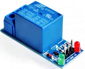
Our circuit operates at 5V and we need something to control 220V AC load, this is where a relay comes handy. This relay when triggered with 5V will toggle an electromechanical switch; this electromechanical switch is capable of candling 220V AC up to 10A current. Hence, our AC load can be connected to the terminals of the relay.
We can also build this circuit without using a relay module. In that case you would have to use an additional transistor like BC547 and drive it using a current limiting resistor to its base.
Circuit Diagram and Explanation:
There are two circuit Diagrams for this RF controlled Home Automation System, one for RF Transmitter as RF remote control for Home Appliances and one for RF Receiver where AC loads are connected. We have previously explained the RF Transmitter and Receiver circuit in detail.
RF Transmitter Circuit:

RF Receiver Circuit:

As you can see the transmitter Circuit consists of the Encoder IC and the Receiver circuit consists of the Decoder IC. Since the transmitter does not need a regulated 5V we have directly powered it with a 9V battery. Whereas in the receiver side we have used a 7805 +5V voltage regulator to regulate 5V from the 9V battery.
Notice that the Address bits A0 to A7 on both the Encoder and Decoder IC are grounded. This means that they are both kept at address 0b00000000. This way they both share the same address and they will act as a pair.
The data pins D10 and D11 (Pin 12 and 13) are connected to switches on the Encoder side and to Relay modules on the decoder side. Based on the position of switch on the encoder side the information will be transferred to decoder and the corresponding light will get toggled.
The two relay modules are powered by the 5V supply provided by the 7805 Regulator and the input pin is connected to the decoder module. The loads are connected through the Relay module so that only when the relay is closed the connection to the load will be complete.
Note: Using a 9V battery to power the receiver set-up might not work properly since the battery is not powerful to supply enough current for relay module. In that case use a 12V battery or adapter.
Warning: High caution is required while handling 220V AC voltage. Make sure the connection is according to circuit and for beginners it is recommended to use junction box (Spike box) that has fuse in it. Also your wires should be of higher gauge so that it can carry the required current and do not connect loads that consume more than 8A current.
Working of RF controlled Home Appliances:
As we saw, the circuit of the project is very simple and can be easily connected in a breadboard, this circuit is built without any microcontroller. I have used two breadboards, one for the transmitter part and the other for the receiver part. I have also used two AC lamps to demonstrate the project. Once you are done with the connections the set-up should look like something like below.
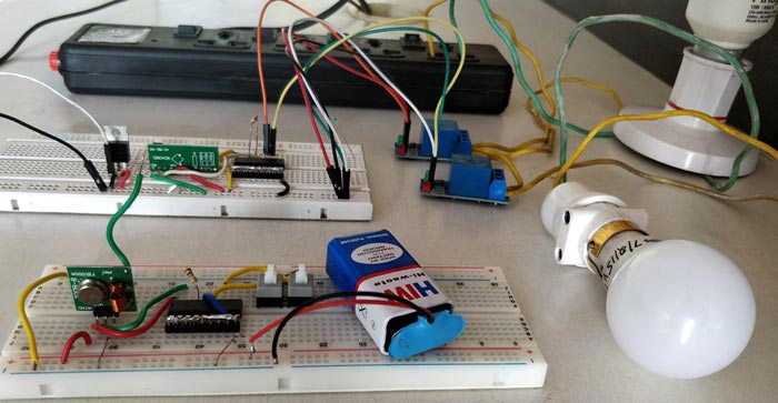
Here the breadboard that is powered by the 9V battery is the transmitter circuit and the other powered by 12V adapter (not shown in pic) is the Receiver module. The AC supply is taken from the black junction box shown above. We also have two relays to control the two AC loads independently. The yellow wire makes up the phase connection and the green wire is the neutral connection.
Once we power on both the circuits we can start toggling the AC loads by using the two switches present on the Transmitter circuit. When the switch one is closed it connects the pin D13 of encoder IC to ground and this value is sent to the decoder IC via the RF medium.
After the decoder receives the value of D13 is also makes its D11 pin to be zero. This means no voltage is given to the input pin of the relay module and the Phase wire will be connected via the Common (Com) and the normally closed (NC) terminals. The same happens in vise versa to turn off the load.
You can now play around this set-up by toggling your switches and your AC loads should also be toggled accordingly. The range of these modules could extend (tested up to 3 meters) by using antenna on the transmitter module. Check the Video below for full Demonstration.
Hope you liked the project and enjoyed building something similar. If you have any doubts you can post them on our forums or on the comments below. We will meet at another interesting project until then happy automating.
Comments
as per your circuit diagram, if the button is pressed, the relay switches itself ON. and it should be off as soon as we release the button. How the relay is ON till the next button press ?
Hi kaushal,
Good question, I have not used buttons here, the white color things are switches. So you press once they stay on, you press again the turn off and stay off till next press. Just like the switch we use to toggle fan or lights in our home
Hi Aswinth,
thank you for the helpfull tutorial. but I still have a question on this statement: "Now, make the Din pin on transmitter high and you will find the Dout pin on receiver also goes high." --> does it mean, by connecting the Din to +5v, then the receiver module will generate +5V in Dout pin too?
Thanks in advance.
Hi , i am using the relay and that is connected to a bulb. but when i send a signal through a raspberry pi rather than doing using classic switches my relay is not reponding. Could you please help me with this.
Hi jimmy,
I think you are using a 5V relay which will not work with Raspberry pi GPIO pins. The Raspberry pi works on 3.3V and hence you cannot drive a relay directly using it. What you can do is, use a BC547 transistor to control the relay
"The range of these modules could extend (tested up to 3 meters) by using antenna"
How long range can be wirelessly operate with this arragement? I need to be controlled more about 100mtr .
If it not possible with this, then what technology other than GSM should i use to get this operation distance except?
tnx

thank you for your ideas