
In this session we are going to develop a RF Remote Control using Raspberry Pi, which can be used to control the Devices wirelessly. We can Switch On and Off the devices using this RF remote control. We have previously developed many projects using RF Module like RF Controlled Robot, Hand Gesture Controlled Robot etc., check them to understand the working of RF Module.
Required Components:
Transmitter Side:
- RF Transmitter (ASK Hybrid Transmitter)
- HT12E IC
- 4 Push buttons
- 750k resistor
- 9 Volt battery
Receiver Side:
- Raspberry Pi
- 16x2 LCD
- 10K POT
- Bread board
- 1K Resistor (Five)
- 33K resistor
- HT12D IC
- RF Receiver (ASK Hybrid Receiver)
- LEDs (Five)
- 10K resistor (Four)
- Connecting wire
- Power Supply
RF Module:
This is a ASK Hybrid Transmitter and receiver module operates at 433Mhz frequency. This module has a crystal stabilized oscillator for maintain accurate frequency control for best range. There we have to need only one antenna externally for this module.
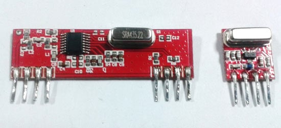
This Module is very cost efficient where long range RF communication is required. This module does not send data using UART communication of PC or microcontroller directly because there is lots of noise at this frequency and its Analog technology. We can use this module with the help of encoder and decoder ICs which extract data from the noise.
The range of transmitter is about 100 meters at maximum supply voltage and for 5 volt the range of transmitter is about 50-60 meter with using a simple wire of single code 17cm length antenna.
RF Transmitter Features:
- Frequency Range: 433 Mhz
- Output Power: 4-16dBm
- Input supply: 3 to 12 volt dc
Pin Description of RF Tx:
- GND - Ground supply
- Data In - This pin accept serial data from encoder
- Vcc - +5 Volt should be connect to this pin
- Antenna - A wrapped connect to this pin for proper transmission of data
RF Receiver Features:
- Sensitivity: -105dBm
- IF Frequency : 1MHz
- Low Power Consumption
- Current 3.5 mA
- Supply voltage: 5 volt
Pin Description of RF Rx:
- GND - Ground
- Data In - This pin give output serial data to Decoder
- Data In - This pin give output serial data to Decoder
- Vcc - +5 Volt should be connect to this pin
- Vcc - +5 Volt should be connect to this pin
- GND - Ground
- GND - Ground
- Antenna - A wrapped connect to this pin for proper Reception of data
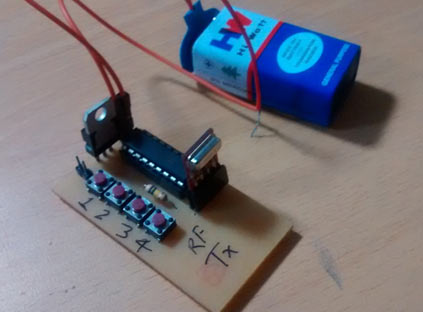
Working Explanation:
Working of this project is very easy. In this project we have used four buttons at transmitter side (serves as remote) to control the four LEDs at Receiver end. When we press any of four buttons then Encoder IC encodes the signal and sends it to RF transmitter and RF Transmitter transmits it in environment. Now RF Receiver receives the transmitted signal and decodes it using Decoder IC HT12D and sends its 4–bit output to Raspberry Pi. Then Raspberry Pi reads these bits and perform related task and glow the respective LED. A buzzer beeps for a second whenever any key is pressed. A 16x2 LCD is also used to display the ‘ON or OFF’ status of all the LEDs.
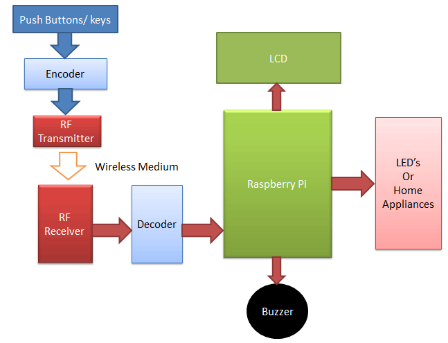
In this Project, we have used four LEDs just for demonstration purpose, we can trigger any task by pressing the respective button at ‘RF Remote’. Like we can also connect AC Home Appliances in place of LEDs, using the Relay and can control those appliances using the same ‘RF Remote’ wirelessly. So this same circuit can work as a RF based Home automation Project using Raspberry Pi. We have previously developed many Home Automation Projects controlled using Bluetooth, DTMF, GSM etc., you can check all here Home Automation Projects.
Circuit Explanation:
Circuit of this Raspberry Pi RF Remote Control is simple which contains Raspberry Pi Board, push button and LCD, RF Pair and encoder/decoder IC. Raspberry Pi controls the LCD, reads input and sends output according to input. We have used Raspberry Pi 3 here, but any Raspberry model should work. Circuit is divided into two parts, one is RF Receiver circuit and other is RF transmitter circuit. Both the circuits are shown in below diagram.

In Receiver part, LCD pin rs, en, d4, d5, d6, d7 are connected at wiringPi GPIO Pin 11, 10, 6, 5, 4, 1 in 4-bit mode. RF Receiver receives the signal from RF Transmitter and HT12D IC decodes it. D8, D9, D10, D11 of HT12D decoder IC are directly connected at wiringPI GPIO pin 25, 24, 23 and 22. Output LEDs are connected at wiringPi GPIO pin 26, 27, 28 and 29. A buzzer is also used for alert on key pressed at wiringPi GPIO 0.
RF transmitter circuit contains the HT12E Encoder IC and 4 push buttons to control the 4 LEDs. In Encoder and Decoder IC all the address lines are connected to ground.
Installing wiringPi Library in Raspberry Pi:
Like in Python we import import RPi.GPIO as IO header file to use the GPIO Pins of Raspberry Pi, here in C language we need to use wiringPi Library to use the GPIO Pins in our C Program. We can install it by using below commands one by one, you can run this command from Terminal or from some SSH clients like Putty (if you are using Windows). Go through our Getting Started with Raspberry Pi tutorial to learn more about handling and configuring the Raspberry Pi.
sudo apt-get install git-core
sudo apt-get update
sudo apt-get upgrade
git clone git://git.drogon.net/wiringPi
cd wiringPi
git pull origin
cd wiringPi
./build
Test the installation of wiringPi library, use below commands:
gpio -v
gpio readall
Programming Explanation:
First of all we include header files and define pins for LCD, then initialize some variables and pins for taking input and LED indications.
#include<wiringPi.h>
#include <wiringSerial.h>
#include<stdio.h>
#include <string.h>
#define RS 11
#define EN 10
#define D4 6
#define D5 5
#define D6 4
#define D7 1
#define led1 26
#define led2 27
#define led3 28
#define led4 29
#define buzz 0
#define d1 25
#define d2 24
#define d3 23
#define d4 22
int flag1=0,flag2=0,flag3=0,flag4=0;
After it we give direction to all used GPIO Pins in void setup() functions.
void setup()
{
   if (wiringPiSetup () == -1)
   {
     clear();
     print("Unable to start");
     setCursor(0,1);
     print("wiringPi");
   }
  pinMode(led1, OUTPUT);
  pinMode(led2, OUTPUT);
  pinMode(led3, OUTPUT);
  pinMode(led4, OUTPUT);
  ... ......
  .... ......
In code we have used digitalRead function to read the output of Decoder and digitalWrite to send the output to LED or device.
.... ....
..... ....
while(1)
   {
        setCursor(0,0);
        print("D1  D2  D3  D4");
        if(digitalRead(d1)==0)
        {
          flag1++;
          setCursor(0,1);
          if(flag1%2==1)
          {
            print("ON ");
            digitalWrite(led1,HIGH);
          }
        .... ....
        ..... ....
Here are some more functions which have been used in this project.
Function void lcdcmd is used for sending command to LCD and void write function is used for sending data to LCD.
Function void clear() is used to clear the LCD, void setCursor is used to set cursor position and void print for sending string to LCD.
Function void begin is used to initialize LCD in 4-bit Mode and void buzzer() for beeping the buzzer.
Check the Full Code for this Raspberry RF Remote Control below.
Complete Project Code
#include<wiringPi.h>
#include <wiringSerial.h>
#include<stdio.h>
#include <string.h>
#define RS 11
#define EN 10
#define D4 6
#define D5 5
#define D6 4
#define D7 1
#define led1 26
#define led2 27
#define led3 28
#define led4 29
#define buzz 0
#define d1 25
#define d2 24
#define d3 23
#define d4 22
int flag1=0,flag2=0,flag3=0,flag4=0;
  void lcdcmd(unsigned int ch)
  {
    int temp=0x80;
    digitalWrite(D4, temp & ch<<3);
    digitalWrite(D5, temp & ch<<2);
    digitalWrite(D6, temp & ch<<1);
    digitalWrite(D7, temp & ch);
    digitalWrite(RS, LOW);
    digitalWrite(EN, HIGH);
    delay(10);
    digitalWrite(EN, LOW);
    digitalWrite(D4, temp & ch<<7);
    digitalWrite(D5, temp & ch<<6);
    digitalWrite(D6, temp & ch<<5);
    digitalWrite(D7, temp & ch<<4);
    digitalWrite(RS, LOW);
    digitalWrite(EN, HIGH);
    delay(10);
    digitalWrite(EN, LOW);
  }
    void write(unsigned int ch)
  {
    int temp=0x80;
    digitalWrite(D4, temp & ch<<3);
    digitalWrite(D5, temp & ch<<2);
    digitalWrite(D6, temp & ch<<1);
    digitalWrite(D7, temp & ch);
    digitalWrite(RS, HIGH);
    digitalWrite(EN, HIGH);
    delay(10);
    digitalWrite(EN, LOW);
    digitalWrite(D4, temp & ch<<7);
    digitalWrite(D5, temp & ch<<6);
    digitalWrite(D6, temp & ch<<5);
    digitalWrite(D7, temp & ch<<4);
    digitalWrite(RS, HIGH);
    digitalWrite(EN, HIGH);
    delay(10);
    digitalWrite(EN, LOW);
  }

  void clear()
  {
     lcdcmd(0x01);
  }
  void setCursor(int x, int y)
  {
    int set=0;
    if(y==0)
    set=128+x;
    if(y==1)
    set=192+x;
    lcdcmd(set);
  }
  void print(char *str)
  {
    while(*str)
    {
     write(*str);
     str++;
    }
  }
  void begin(int x, int y)
  {
    lcdcmd(0x02);
    lcdcmd(0x28);
    lcdcmd(0x06);
    lcdcmd(0x0e);
    lcdcmd(0x01);
  }

 void buzzer()
{
     digitalWrite(buzz, HIGH);
     delay(1000);
     digitalWrite(buzz, LOW);
}
  void setup()
{
   if (wiringPiSetup () == -1)
   {
     clear();
     print("Unable to start");
     setCursor(0,1);
     print("wiringPi");
   }
  pinMode(led1, OUTPUT);
  pinMode(led2, OUTPUT);
  pinMode(led3, OUTPUT);
  pinMode(led4, OUTPUT);
  pinMode(buzz, OUTPUT);
  pinMode(RS, OUTPUT);
  pinMode(EN, OUTPUT);
  pinMode(D4, OUTPUT);
  pinMode(D5, OUTPUT);
  pinMode(D6, OUTPUT);
  pinMode(D7, OUTPUT);
  pinMode(d1, INPUT);
  pinMode(d2, INPUT);
  pinMode(d3, INPUT);
  pinMode(d4, INPUT);
  digitalWrite(led1, LOW);
  digitalWrite(led2, LOW);
  digitalWrite(led3, LOW);
  digitalWrite(led4, LOW);
  digitalWrite(buzz, LOW);
  begin(16,2);
}

//void loop()
void main()
{
   setup();
   clear();
   print("  RF Module ");
   setCursor(0,1);
   print(" Interfacing ");
   delay(2000);
   clear();
   print("Raspberry Pi");
   setCursor(0,1);
   print("Circuit Digest");
   delay(2000);
   clear();
   print("System Ready");
   delay(1000);
   clear();
  setCursor(0,1);
  print("OFF OFF OFF OFF");
   while(1)
   {
        setCursor(0,0);
        print("D1  D2  D3  D4");
        if(digitalRead(d1)==0)
        {
          flag1++;
          setCursor(0,1);
          if(flag1%2==1)
          {
            print("ON ");
            digitalWrite(led1,HIGH);
          }
          else
          {
            print("OFF");
            digitalWrite(led1,LOW);
          }
          buzzer();
          while(digitalRead(d1)==0);
        }
        else if(digitalRead(d2)==0)
        {
          flag2++;
          setCursor(4,1);
          if(flag2%2==1)
          {
            print("ON ");
            digitalWrite(led2,HIGH);
          }
          else
          {
            print("OFF");
            digitalWrite(led2,LOW);
          }
          buzzer();
          while(digitalRead(d2)==0);
        }
         else if(digitalRead(d3)==0)
        {
          flag3++;
          setCursor(8,1);
          if(flag3%2==1)
          {
            print("ON ");
            digitalWrite(led3,HIGH);
          }
          else
          {
            print("OFF");
            digitalWrite(led3,LOW);
          }
         buzzer();
          while(digitalRead(d3)==0);
        }
        else if(digitalRead(d4)==0)
        {
          flag4++;
          setCursor(12,1);
          if(flag4%2==1)
          {
            print("ON ");
            digitalWrite(led4,HIGH);
          }
          else
          {
            print("OFF");
            digitalWrite(led4,LOW);
          }
          buzzer();
          while(digitalRead(d4)==0);
        }
}
}
Comments
C programs are much better than Python (although not so easy). There are many Python examples on that topic.

in raspberry pi normally we use python software ,but where u have written c program in Rpi....pls reply