
An automatic toll gate system using Arduino revolutionises traditional toll collection by eliminating manual intervention. The “automatic toll gate system project” demonstrates how simple sensors and a microcontroller can automate a real-life process like toll collection, making it an ideal project for school students and anyone just starting in the field of electronics.
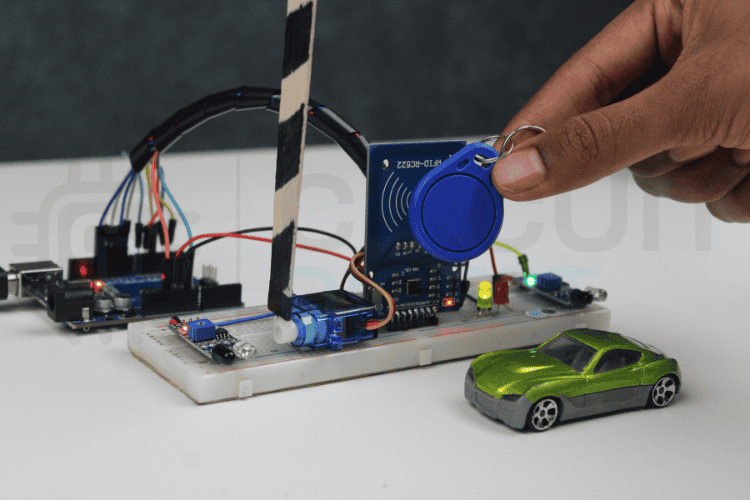
In this setup, an RFID card acts as a digital payment card that carries a balance. When a vehicle arrives, the entry IR Sensor detects it, and the RFID Reader scans the card to check if there is enough balance available. If the amount is sufficient, the Arduino automatically deducts the toll, and the servo motor opens the gate. For a practical RFID-based attendance system project using Arduino, check out this comprehensive guide that walks you through the entire implementation process. A second IR Sensor confirms when the vehicle has passed, after which the gate closes again. This automatic toll gate system project using Arduino shows how automation can make toll collection faster, easier, and completely hands-free. In this comprehensive guide, you'll learn to build an automated toll gate system that automatically detects vehicles, processes RFID card payments, deducts toll amounts, and controls gate operation. This tutorial is created by the CircuitDigest engineering team. Our experts focus on creating practical, hands-on tutorials that help makers and engineers master Raspberry Pi projects, Arduino projects and IoT projects.
This automatic toll gate system project using Arduino is simple, beginner-friendly, and perfect for school students as well as anyone entering the electronics field. It also relates to other similar projects, such as How to Build a Smart Toll Tax System Using Arduino Uno, RFID-Based Toll Collection System, giving learners more options to explore automated toll solutions.
Table of Contents
Components Required for Automatic Toll Gate System Project
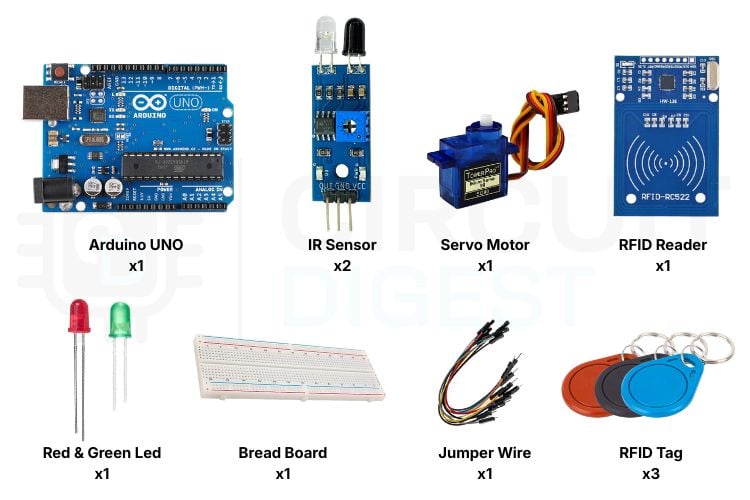
This automatic toll gate system project using Arduino shows how simple sensors and a microcontroller can automate toll collection in a smart and efficient way. The project uses simple electronic components like IR sensors, an RFID reader, a Servo Motor and LEDs to build an automated toll gate system. Building this automatic toll gate system using Arduino requires affordable, readily available electronic components. Each component plays a specific role in creating this automated toll gate system.
| Components | Description | Qty |
| A microcontroller is used to read sensors, process RFID data, and control the servo gate. | 1 | |
| Reads RFID cards and sends their unique ID to the Arduino. Used as a digital payment card scanner. | 1 | |
| RFID Tags/Cards | Stored with balance values. Used to simulate vehicle payment cards. | 3 |
| IR Sensor Modules | Detects vehicle presence at entry and exit of the toll gate. | 2 |
| Servo Motor | Acts as the automatic gate that opens and closes. | 1 |
| Red LED | Indicates access denied or gate closed. | 1 |
| Green LED | Indicates payment success or gate open | 1 |
| Jumper Wires | Used for circuit connections. | - |
| Breadboard | For connecting components without soldering. | 1 |
| 5V Power Supply / USB power | Powers the Arduino and connected components. | 1 |
Key Component Specifications for Automatic Toll Gate System
» RFID RC522: Operating frequency 13.56 MHz, read range up to 5 cm, and SPI interface communication
» IR Sensors: Detection range 2-30 cm (adjustable), digital output signal, 5V operating voltage
» SG90 Servo: Rotation range 0-180 °, operating voltage 4.8-6V, torque 1.8kg/cm
» Arduino Uno: ATmega328P processor, 14 digital I/O pins, 6 PWM outputs, 32KB flash memory
Advantages of Arduino-Based Automated Toll Gate System
✓ Affordable Solution
Total component costs are less than $30, making the project affordable to educators & small-scale projects.
✓ Easy to Use
Simple circuit connections are great for beginners, and the components are well supported with Arduino code documents.
✓ Contactless Use
Using RFID technology means that end-users do not have to handle cash, which helps increase hygiene, and the speed of transactions.
✓ Scalable Design
The components can easily be expanded with many add-on features, including LCD displays, WiFi connectivity, and database logging.
Step-by-Step Working of the Automatic Toll Gate System Project
Understanding the operational workflow of this automated toll gate system helps you grasp how Arduino coordinates multiple sensors and actuators to create a seamless toll collection experience. The automatic toll gate system project using Arduino uses an organised approach that employs different kinds of sensors and actuators. There are several ways in which the Automated Toll Collection System Works:
Automatic Toll Gate System Workflow
⇒ Detection of Vehicles Entering: As the first IR sensor registers an incoming vehicle, it triggers an authentication process.
⇒ RFID Scanning: Once at the reader, the user taps their RFID card for the Arduino to read its unique identification (UID) number.
⇒ Validation and Verification of Cards: The system will validate whether or not the RFID card is stored in the database, and it will also verify that there is enough money on the RFID card for toll payment.
⇒ Decision Regarding Payment Processing:
- If there is an adequate balance, the toll will be automatically deducted from the card.
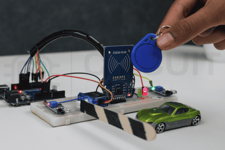
- If there is no adequate balance, the system denies access and illuminates a red LED light.
- If an unknown RFID card is present, the system will reject the transaction and provide an error message.
⇒ Electronic Gate Operation: Once a payment is verified as successful, the gate will electronically operate by rotating a servo to allow 90 degrees of movement in an open position, along with the green LED indicating successful authorisation.
⇒ Vehicle Passage Detection: Upon total vehicle clearance from authorised toll areas, detection will cease via the second IR sensor located at the exit.
⇒ Automatic Gate Close: The electronic gate will close (return to closed) automatically upon the exit of a vehicle.
⇒ Gate Reset /Ready to Process a Transaction: The electronic toll collection system is reset, or returns to an idle state, to allow processing of the next vehicle transaction.
This workflow shows how the automatic toll gate system project uses basic sensors and an RFID-based payment method to automate the toll process. By detecting vehicles, validating cards, handling payments, and controlling the gate automatically, the setup ensures smooth, quick, and hands-free toll collection. Once the vehicle passes, the system resets and gets ready for the next one, making the entire operation efficient and easy to use.
Automatic Toll Gate System Block Diagram
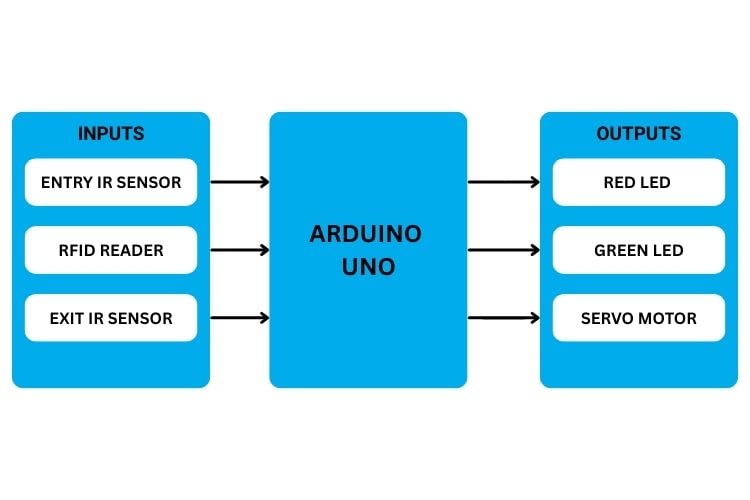
The Automatic Toll Gate System Block Diagram indicates that the Arduino Uno functions as the 'brain' of the system, collecting and processing sensor input, and using that input to control the outputs of the system.
As illustrated in the block diagram above, three sensors relay information to the Arduino: the Entry Infrared (IR) Sensor detects an approaching vehicle, the RFID reader reads the payment card, and the Exit IR Sensor detects a vehicle leaving the parking area. Therefore, based on this input from the three sensors, the Arduino controls the operation of three outputs: 1) when payment is not made, the red LED will illuminate. When payment is successfully accepted, the green LED will illuminate; and lastly, when the servo motor opens the toll gate, the vehicle will be allowed to exit the parking area.
Automatic Toll Gate Circuit Diagram and Pin Connections
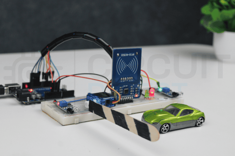
The automatic toll gate circuit diagram shows the complete wiring schematic for connecting all components in this automatic toll gate system project using Arduino. The RFID Reader is connected with the SPI pins, and the IR sensors are attached to the digital input pins. The servo motor is connected to the PWM pin to control the gate's movement, and the LEDs are also connected to the digital output pins. The automatic toll gate circuit diagram shows all electrical connections between the Arduino microcontroller and peripheral components.
All components share a common 5V supply and ground line from the Arduino, except the RFID reader, which is connected to the 3.3V supply line.

Complete Pin Connection Tables for Automatic Toll Gate System
Here is the detailed breakdown of the pin connection between the different sets of sensors and the Arduino. This includes all the necessary pins for the RFID reader, IR sensors, LEDs, and the servo motor to be connected with the Arduino, in a tabular format for easy reference.
RFID RC522 Reader Pin Configuration
| RFID Pins | Arduino Pins |
| SDA | 10 |
| SCK | 13 |
| MOSI | 11 |
| MISO | 12 |
| GND | GND |
| RST | 9 |
| 3.3V | 3.3V |
RFID Reader: This reads the RFID card tapped by the driver and verifies whether the card is valid and has enough balance for toll payment.
For further guidance, you can refer to the Arduino RFID Tutorial: Complete RC522 Guide with Code & Project, which provides clear wiring diagrams and sample code for beginners. LED indicators provide clear visual feedback in the automated toll gate system, helping users understand the system status at a glance. You can learn how to build a secure access solution by following this step-by-step RFID door lock system using Arduino tutorial.
LED Indicator Wiring
| LEDs | Arduino Pins |
| Red LED | 6 |
| Green LED | 7 |
| Both LEDs GND | GND |
LEDs: The red and green LEDs indicate the system status, red shows that the gate is closed or access is denied, while green lights up when the gate is open, and the vehicle is allowed to pass. The IR sensors in this automatic toll gate system project provide obstacle detection capabilities.
IR Sensor Module Connections
IR Sensors | Arduino Pins |
| Entry IR OUT | 6 |
| Exit IR OUT | 7 |
| VCC | 5V |
| GND | GND |
IR Sensors: These detect the presence of a vehicle at the entry and exit points, allowing the system to know when to start and when to close the gate.
Servo Motor Gate Control
| SERVO Motor | Arduino Pins |
Signal | 5 |
| VCC | 5V |
| GND | GND |
Servo Motor: This acts as the toll gate, opening when payment is successful and closing again after the vehicle passes. The servo motor acts as the physical toll gate barrier in this automatic toll gate system project using Arduino.
A helpful guide for beginners is the tutorial How to Control Servo Motor using Arduino, which provides step-by-step instructions.
Automatic Toll Gate System Project Using Arduino Code Explained
Here is the detailed breakdown of the code. It explains important parts of the program, from reading the sensor to processing the RFID card and controlling the servo gate. The automatic toll gate system project using Arduino code is structured into logical sections that handle different aspects of the automated toll gate system.
1. Library Inclusions and Dependencies
These libraries provide essential functions for the automatic toll gate system using Arduino:
#include <SPI.h>
#include <MFRC522.h>
#include <Servo.h>
This part here loads the required libraries for the project. The SPI.h library establishes communication between Arduino and the RFID reader using the SPI Protocol. The MFRC522.h library provides all the built-in functions needed to control and detect RFID cards and read their unique IDs. Finally, the Servo.h used to control the servo motor, which acted as the toll gate.
2. Pin Definitions and Hardware Mapping
#define SS_PIN 10
#define RST_PIN 9
#define IR_ENTRY 2
#define IR_EXIT 3
#define LED_RED 6
#define LED_GREEN 7
#define SERVO_PIN 5
Here, the pin connection for RFID, IR sensors, LEDs, and the servo motor is defined. This section defines all hardware connections used in the automatic toll gate circuit diagram, making code maintenance easier and improving readability.
3. Object Instantiation and Global Variables
Servo gateServo;
MFRC522 rfid(SS_PIN, RST_PIN);
const int GATE_OPEN = 90;
const int GATE_CLOSED = 0;
byte Tag1[4] = {...};
byte Tag2[4] = {...};
byte Tag3[4] = {...};
int balance1 = 500;
int balance2 = 300;
int balance3 = 0;
int tollAmount = 20;
In this part, objects for the RFID module and the servo motor are created. RFID tags' IDs are stored in arrays, along with their wallet balances. Gate positions and the toll amount are also defined in this set of code. These values will be available throughout the program and can be used repeatedly during the program
4. Setup Function - System Initialisation
void setup() {
 Serial.begin(9600);
 SPI.begin();
 rfid.PCD_Init();
 pinMode(IR_ENTRY, INPUT);
 pinMode(IR_EXIT, INPUT);
 pinMode(LED_RED, OUTPUT);
 pinMode(LED_GREEN, OUTPUT);
 gateServo.attach(SERVO_PIN);
 gateServo.write(GATE_CLOSED);
}
The setup() Function initialises all the modules, like the SPI bus, RFID reader, servo motor, and the serial monitor. It configures the IR sensors' inputs and outputs. The gate servo motor is set to a closed position. When the system is ready, it prints a startup message and initiates the hardware for operation. These global variables store RFID card credentials and balances for the automated toll gate system.
5. Main Loop - Continuous Operation
void loop() {
 digitalWrite(LED_RED, HIGH);
 digitalWrite(LED_GREEN, LOW);
 gateServo.write(GATE_CLOSED);
 if (digitalRead(IR_ENTRY)) {
   Serial.println("\nCar at entry. Waiting for RFID...\n");
   while (digitalRead(IR_ENTRY) == HIGH) {
     if (!rfid.PICC_IsNewCardPresent() || !rfid.PICC_ReadCardSerial()) {
       delay(100);
       continue;
     }
     Serial.print("RFID Tag Detected: ");
     printUID(rfid.uid.uidByte);
     Serial.println();
     bool is1 = uidEquals(rfid.uid.uidByte, Tag1);
     bool is2 = uidEquals(rfid.uid.uidByte, Tag2);
     bool is3 = uidEquals(rfid.uid.uidByte, Tag3);
     if (is1) {
       processCard(balance1, 1);
     } else if (is2) {
       processCard(balance2, 2);
     } else if (is3) {
       processCard(balance3, 3);
     } else {
       Serial.println("Unknown Card -- Access Denied");
       denyAccess();
     }
     waitForCardRemoval();
     rfid.PICC_HaltA();
     rfid.PCD_StopCrypto1();
     delay(200);
   }
 }
}
The loop() function resets the system by turning on the red LED, turning off the Green LED. Initially, the gate is closed, and then it checks for any entry in the IR sensor, and if a vehicle is detected, then the system starts to read the RFID card. When a card is scanned, the UID of the card is obtained and compared with the stored cards' IDs. If the card ID is matched and has enough balance, only then is the toll payment processed, and the gate is opened. If there is a mismatch between the card ID and the stored ID then the gate does not open. The setup function initialises all hardware components required for the automatic toll gate system project using Arduino.
Serial Monitor Output - Automatic Toll Gate System Testing
The serial monitor provides real-time feedback for debugging and monitoring the automatic toll gate system project. These logs help verify that the system is functioning correctly and make debugging easier during development.
Below is the sample serial output format:
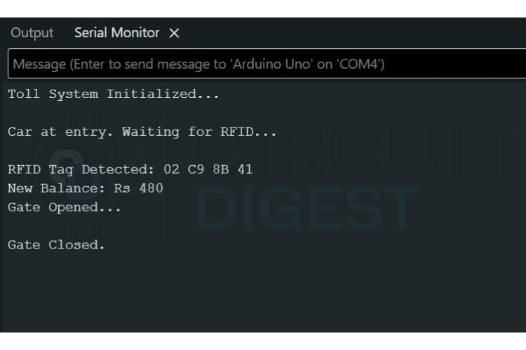
The first output shows the complete flow of a successful vehicle entry. When the IR sensor detects a car and then the system scans the RFID tag and verifies the card as authorised. After confirming the balance and deducting the toll amount, the Arduino opens the servo-controlled gate, allowing the vehicle to pass and then closes the gate. Finally, the system resets and waits for the next vehicle.
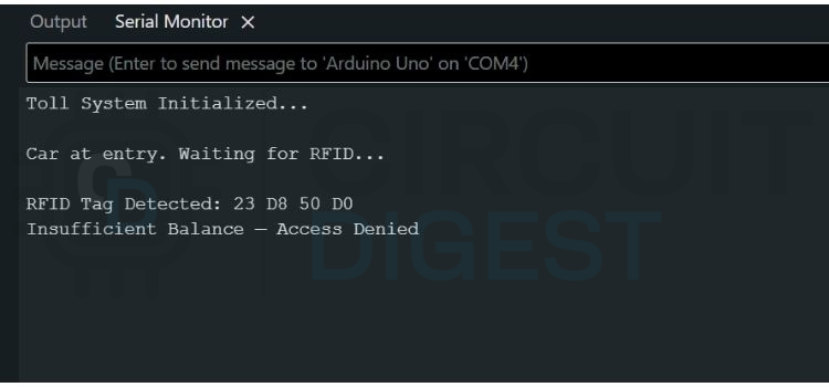
In the insufficient balance scenario, the system reads the RFID card, but after checking the stored balance, it finds that the amount is not enough to pay the toll. The Arduino then denies access and displays a warning message in the Serial Monitor.
Real-World Applications of Automatic Toll Gate Systems
The automated toll gate system technology has numerous practical applications beyond basic toll collection:
» Automated toll collection at highway toll plazas allows for speedier vehicle movement through heavy traffic by reducing the delay caused by manual cash transactions on highways.
» Automated entry/exit using RFID technology is now commonplace in several operational settings, including shopping malls, airport terminals, and office buildings, as a means to facilitate efficient management of parking spaces.
» RFID technology is increasingly used in gated communities as a means for identifying vehicles of residents (or individuals permitted access) and for controlling access to gated areas.
» In warehousing and manufacturing operations, RFID automated gates provide not only a means to track vehicles entering and leaving an industrial facility but also provide autonomously controlled authorisation.
» RFID systems are used in institutions of higher education, both to identify students entering a campus and to monitor where they park their vehicles on campus.
» Automated gates at stadiums, concert halls and other similar venues simplify and speed up ticket validation for event attendees and improve management of attendees entering the venue.
Troubleshooting Common Issues in the Automatic Toll Gate System
Problem | Possible Causes | Solutions |
|---|---|---|
RFID reader not detecting cards | • Wrong voltage (using 5V instead of 3.3V) | • Verify 3.3V power connection |
Servo motor not moving | • Insufficient power supply | • Use external 5V power for servo (min 500mA) |
IR sensors always triggered | • Incorrect sensitivity adjustment | • Adjust potentiometer on IR module |
Gate closes before vehicle passes | • Exit IR sensor not working | • Test exit sensor independently |
Balance not updating correctly | • Variable not passed by reference | • Use & operator in function parameters |
Multiple cards same UID | • Using default UID from examples | • Read actual UID using RFID dump code |
Future Enhancements for the Automatic Toll Gate System Project
The basic automatic toll gate system project using Arduino can be enhanced with advanced features:
∗ Integrating a 16×2 or 20×4 LCD display to allow users to see their balance, toll amounts, and messages from the system will help them to interact with the system more effectively.
∗ Utilising the ESP8266 or ESP32 chip for internet connectivity through WiFi and the Internet of Things will provide the ability to record and store data on various cloud-based platforms such as ThingSpeak or Firebase.
∗ A mobile application will be developed so users can check balances, view a list of their transactions, and monitor their systems remotely.
∗ All transaction records will be logged on an SD card or through an online database that can be reviewed later for audit purposes and analytics.
∗ The OCR (Optical Character Recognition) technology included with a camera module will be used to identify license plates and connect them to customers to verify their identity, if required.
∗ In order to operate without being connected to a traditional power source, solar panels and batteries will be utilised at the toll booths.
∗ The toll systems will be developed to support a specific lane and have a central management system.
∗ Variable toll rates will be established based on how late the customer arrives at the toll booth or the type of vehicle they are using.
GitHub Repository and Source Files
Access the complete source code, circuit diagrams, and documentation for this automatic toll gate system project using Arduino.


Frequently Asked Questions - Automatic Toll Gate System Project Using Arduino
⇥ 1. What is an automatic toll gate system with the use of Arduino?
It is an IoT project that uses Arduino and automates tolling payments made via an RFID card. It uses an IR sensor and a servo motor-controlled gate that opens automatically upon successful completion of payments.
⇥ 2. What is the automatic toll gate circuit diagram for Arduino connections?
From the automatic toll gate circuit diagram, it is evident that there are connections from RFID SPI pins (10, 11, 12, 13), IR sensor pins 2 and 3, servo 5, and LEDs 6 and 7. Additionally, RFID requires 3.3V, and the rest operate with 5V.
⇥ 3. Is it possible for a beginner to develop an automatic toll gate system project?
Yes, it is very beginner-friendly. It needs some basic knowledge about programming an Arduino board, making connections on a breadboard without any soldering, and documented coding. Students and enthusiasts can attempt it within 2-3 hours.
⇥ 4. How does the RFID card balance verification function within the system?
The UIDs are stored in Arduino memory with respective balance variables. Once scanned, it compares the UID, then matches it with the balance and against the toll cost ($20 as default), opening the gate once paid. An insufficient balance will result in an access denial.
⇥ 5. How are automatic toll gate systems used in practice?
Toll gates are commonly found on highways, parking lots, gated communities, business parks, schools, and industrial sites. They can also be found at shopping centers and airports for parking, as well as for longer-term vehicle storage.
⇥ 6. Why isn't my RFID reader reading cards at the toll gate system?
Some common causes are incorrect power supply wiring (3.3 volts vs. 5 volts), loose connection on the SPI cable, incorrect assignment of the PINs in the coding, malfunctioning RFID modules, or low sensitivity antennas. To troubleshoot this issue, check all connections on the circuit diagram and check for initialisation messages on your serial monitor.
⇥ 7. How can I improve my automatic toll gate system project?
Include a 16x2 LCD display for user messages, integrate an ESP8266 module for IoT data logging on cloud services, develop an app for balance management, include SD card logging for transactions, integrate a camera for license number recognition, or integrate solar panels for autonomous functioning.
Explore DIY electronic projects featuring step-by-step guides, circuit diagrams, and real-world builds for beginners and advanced makers alike.
I hope you liked this article and learned something new from it. If you have any doubts, you can ask in the comments below or use our CircuitDigest forum for a detailed discussion.
RFID-Based Projects using EM18 RFID Reader
Previously, we have used RFID to build many interesting projects. If you want to know more about those topics, links are given below.

Fingerprint-based Car Ignition System using Arduino and RFID
In this Fingerprint-Based Car Ignition System, we are using Arduino with an R305 Fingerprint sensor and an EM18 RFID reader.

IoT-based Event Management System using RFID and ThingSpeak
Build an RFID-based IoT-enabled event Management System that not only monitors the entry log but, with the help of IoT technology but can also send the Log and Entry data directly to a dedicated server that can handle all the authentication, authorisation, and management, making the whole process seamless.

How to Connect RFID with STM32 Microcontroller
Build an RFID-based IoT-enabled event Management System that not only monitors the entry log, but with the help of IoT technology but can also send the Log and Entry data directly to a dedicated server that can handle all the authentication, authorisation, and management, making the whole process seamless.
Complete Project Code
#include <SPI.h>
#include <MFRC522.h>
#include <Servo.h>
// RFID Pins
#define SS_PIN 10
#define RST_PIN 9
// IR sensors
#define IR_ENTRY 2
#define IR_EXIT 3
// LEDs
#define LED_RED 6
#define LED_GREEN 7
// Servo
#define SERVO_PIN 5
Servo gateServo;
MFRC522 rfid(SS_PIN, RST_PIN);
// Servo positions
const int GATE_OPEN = 90;
const int GATE_CLOSED = 0;
// ---- STORED RFID CARDS (4-byte UIDs) ----
byte Tag1[4] = {0x02, 0xC9, 0x8B, 0x41};
byte Tag2[4] = {0x09, 0xD6, 0x8B, 0x5A};
byte Tag3[4] = {0x23, 0xD8, 0x50, 0xD0};
// ---- BALANCES ----
int balance1 = 500;
int balance2 = 300;
int balance3 = 0;
int tollAmount = 20;
void setup() {
Serial.begin(9600);
SPI.begin();
rfid.PCD_Init();
pinMode(IR_ENTRY, INPUT);
pinMode(IR_EXIT, INPUT);
pinMode(LED_RED, OUTPUT);
pinMode(LED_GREEN, OUTPUT);
gateServo.attach(SERVO_PIN);
gateServo.write(GATE_CLOSED);
digitalWrite(LED_RED, HIGH);
digitalWrite(LED_GREEN, LOW);
Serial.println("Toll System Initialized...");
}
bool uidEquals(byte *a, byte *b) {
for (byte i = 0; i < 4; i++)
  if (a[i] != b[i]) return false;
return true;
}
void printUID(byte *uid) {
for (byte i = 0; i < 4; i++) {
  if (uid[i] < 0x10) Serial.print("0");
  Serial.print(uid[i], HEX);
  if (i < 3) Serial.print(" ");
}
}
void waitForCardRemoval() {
while (rfid.PICC_IsNewCardPresent() && rfid.PICC_ReadCardSerial()) {
  delay(50);
}
}
void loop() {
digitalWrite(LED_RED, HIGH);
digitalWrite(LED_GREEN, LOW);
gateServo.write(GATE_CLOSED);
if (digitalRead(IR_ENTRY)) {
  Serial.println("\nCar at entry. Waiting for RFID...\n");
  while (digitalRead(IR_ENTRY) == HIGH) {
    if (!rfid.PICC_IsNewCardPresent() || !rfid.PICC_ReadCardSerial()) {
      delay(100);
      continue;
    }
    Serial.print("RFID Tag Detected: ");
    printUID(rfid.uid.uidByte);
    Serial.println();
    bool is1 = uidEquals(rfid.uid.uidByte, Tag1);
    bool is2 = uidEquals(rfid.uid.uidByte, Tag2);
    bool is3 = uidEquals(rfid.uid.uidByte, Tag3);
    // Process each card
    if (is1) {
      processCard(balance1, 1);
    } else if (is2) {
      processCard(balance2, 2);
    } else if (is3) {
      processCard(balance3, 3);
    } else {
      Serial.println("Unknown Card -- Access Denied");
      denyAccess();
    }
    // Cleanup and wait for removal
    waitForCardRemoval();
    rfid.PICC_HaltA();
    rfid.PCD_StopCrypto1();
    delay(200);
  }
}
}
void processCard(int &balance, int cardNumber) {
  if (balance >= tollAmount) {
  balance -= tollAmount;
  Serial.print("New Balance: Rs ");
  Serial.println(balance);
  openGateAndWaitExit();
}
else {
  Serial.println("Insufficient Balance -- Access Denied");
  denyAccess();
}

}
void denyAccess() {
for (int i = 0; i < 3; i++) {
  digitalWrite(LED_RED, LOW);
  delay(150);
  digitalWrite(LED_RED, HIGH);
  delay(150);
}
}
void openGateAndWaitExit() {
digitalWrite(LED_RED, LOW);
digitalWrite(LED_GREEN, HIGH);
gateServo.write(GATE_OPEN);
Serial.println("Gate Opened...\n");
// Wait for car to reach exit sensor
while (digitalRead(IR_EXIT) == LOW) delay(50);
// Wait for car to clear exit sensor
while (digitalRead(IR_EXIT) == HIGH) delay(50);
delay(500);
// Close gate
gateServo.write(GATE_CLOSED);
digitalWrite(LED_GREEN, LOW);
digitalWrite(LED_RED, HIGH);
Serial.println("Gate Closed.");
}
