
In this tutorial, we will design a system to read the RFID cards using STM32 and RFID Reader. RFID stands for Radio Frequency Identification which reads information by using radio frequencies. RFID’s are used in many authentication systems like elevator parking system, automated toll collection, maintaining patient information in hospitals, automated data collection etc.
In this tutorial, we will learn how to interface an EM-18 RFID Reader Module and read the unique ID of RFID tags using STM32F103C8 microcontroller. We have previously interfaced RFID with other microcontrollers:
- RFID Interfacing with Arduino
- RFID Interfacing with PIC Microcontroller
- RFID Interfacing with MSP430 Launchpad
- RFID Interfacing with 8051 Microcontroller
- RFID and Raspberry Pi Based Attendance System
Components Required
- STM32F103C8 (Blue Pill Board)
- EM-18 RFID Reader Module
- RFID Cards
- 16x2 LCD Display Module
- Bread Board
- Connecting Wires
Before interfacing RFID with STM32, first we will learn about RFID tags and RFID reader.
RFID Tags
RFID tags are made up of a microchip with a coiled antenna that can communicate with a nearby reader wirelessly. Different kind of RFID tags with a different kind of shapes and sizes are available in the market. Few of them use different frequency for communication purpose. We will use 125Khz Passive RFID cards which holds the unique ID data.
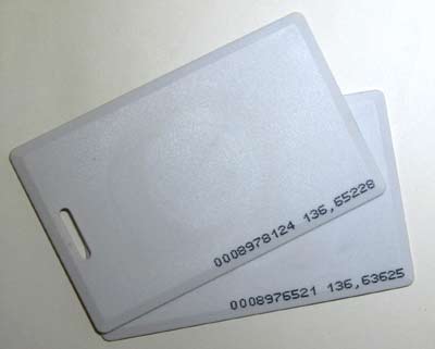
You can observe a coil and a microchip present inside the tag when you place a RFID tag in front of a bright light.
There are basically two types of RFID tags: Passive and Active
Passive RFID tags draw power from the magnetic field that was created by the reader module like EM-18 and use it to power the microchip’s circuits. The chip then sends information to the reader.
Active RFID tags requires separate power supply and contain up to 1MB of read/write memory.
https://circuitdigest.com/microcontroller-projects/rfid-interfacing-with-msp430-launchpad
EM-18 RFID Reader
Each RFID card has a unique ID embedded in it and a RFID reader is used to read the RFID card no. EM-18 RFID reader operates at 125 KHz and it comes with an on-chip antenna and it can be powered with 5V power supply. It provides serial output along with weigand output. The range is around 8-12cm. serial communication parameters are 9600bps, 8 data bits, 1 stop bit. This wireless RF Identification is used in many systems like
Check all the RFID Projects here.
The output provided by EM-18 RFID reader is in 12 digit ASCII format. Out of 12 digits first 10 digits are card number and the last two digits are the XOR result of the card number. Last two digits are used for error checking.


For example, card number is 0200107D0D62 read from the reader then the card number on the card will be as below.
02 – preamble
00107D0D = 1080589 in decimal.
62 is XOR value for (02 XOR 00 XOR 10 XOR 7D XOR 0D).
Hence number on the card is 0001080589.
Pin Details of EM-18
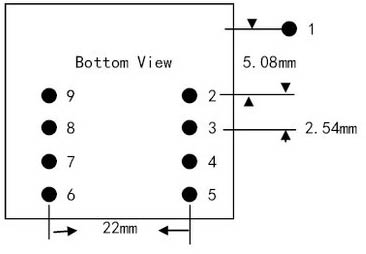
EM-18 RFID reader has nine pins. Among nine pins, 2 pins are not connected, so we basically have to consider seven terminals. The table below shows Pin description of EM-18.
|
Pin Number |
Pin Name |
Use |
|
1 |
VCC |
POSITIVE |
|
2 |
GND |
GROUND |
|
3 |
BUZZ |
Connected to BUZZER |
|
4 |
NC |
No Connection |
|
5 |
NC |
No Connection |
|
6 |
SEL |
SEL=1 (RS232) SEL=0 (WEIGAND) |
|
7 |
TX |
DATA is given out through TX of RS232 |
|
8 |
DATA1 |
WEIGAND interface DATA HIGH pin |
|
9 |
DATA0 |
WEIGAND interface DATA LOW pin |
Specifications of EM-18 RFID Module
- Read distance: 10cm
- Operating temperature: 0ºC to +80ºC
- Communication parameter: 9600bps
- Current Consumption: <50mA
- Operating frequency: 125 kHz
- Operating Voltage: 5v
Circuit Diagram and Connections

Connections between STM32F103C8 & 16x2 LCD
|
LCD Pin No |
LCD Pin Name |
STM32 Pin Name |
|
1 |
Ground (Gnd) |
Ground (G) |
|
2 |
VCC |
5V |
|
3 |
VEE |
Pin from Centre of Potentiometer |
|
4 |
Register Select (RS) |
PB11 |
|
5 |
Read/Write (RW) |
Ground (G) |
|
6 |
Enable (EN) |
PB10 |
|
7 |
Data Bit 0 (DB0) |
No Connection (NC) |
|
8 |
Data Bit 1 (DB1) |
No Connection (NC) |
|
9 |
Data Bit 2 (DB2) |
No Connection (NC) |
|
10 |
Data Bit 3 (DB3) |
No Connection (NC) |
|
11 |
Data Bit 4 (DB4) |
PB0 |
|
12 |
Data Bit 5 (DB5) |
PB1 |
|
13 |
Data Bit 6 (DB6) |
PC13 |
|
14 |
Data Bit 7 (DB7) |
PC14 |
|
15 |
LED Positive |
5V |
|
16 |
LED Negative |
Ground (G) |
Connections between STM32F103C8 & EM-18 Reader Module
|
EM-18 Reader Module |
STM32F103C8 |
|
VCC |
+5V |
|
GND |
GND |
|
TX |
PA10 |
Programming STM32F103C8 for reading RFID
In our previous tutorial, we learned about Programming STM32F103C8T6 Board using USB Port . So we don’t need a FTDI programmer now. Simply connect it to PC via USB port of STM32 and start programming with ARDUINO IDE. Programming your STM32 in ARDUINO IDE to read RFID tag is very simple
1. First, include LCD display library for using LCD display functions. Then define LCD pins and initialize the LCD display. To know more about interfacing LCD with STM32F103C8 follow the link.
#include <LiquidCrystal.h>
const int rs = PB11, en = PB10, d4 = PB0, d5 = PB1, d6 = PC13, d7 = PC14;
LiquidCrystal lcd(rs, en, d4, d5, d6, d7);
2. Next in void setup()
We need to set the LCD display mode as 16x2 and start serial communication at baud rate 9600 with the pin PA10 (This is the SERIAL1 Communication port RX1 of the STM32F103C8 which is connected with the EM-18 TX pin.
 lcd.begin(16, 2);
 Serial1.begin(9600);
 pinMode(PA10,INPUT);
3. Next display welcome message and clear after some time.
lcd.print("CIRCUIT DIGEST");       //Prints at LCD display
 lcd.setCursor(0, 1);               //Set courser to second line
lcd.print("RFID WITH STM32");      //Prints at LCD display
 delay(5000);                       //Delay for 5 Seconds
 lcd.clear();                       //Clears LCD display
 lcd.setCursor(0,0);                //Sets cursor at First Line
 lcd.print("RFID TAG NO:");         //Prints at LCD display
lcd.setCursor(0,1);                //Sets cursor at Second line
4. In void loop()
Once the data from EM-18 RFID Reader Module (Tag ID) is available at the serial pin of STM32F103C8 the character is stored bit by bit and displayed one by one on LCD display.
{
   while(Serial1.available() && count < 12)
  {

     RFID[count] = Serial1.read();
     count++;

     lcd.print(RFID[count]);

     if (count==12)
              {
                   lcd.print("             ");
                   count = 0;
                   lcd.setCursor(0, 1);
                }
 }
}
Now just upload the complete code in STM32 and your system is ready to work. Just place any RFID tag over RFID reader and you will see the Tag ID appearing on the 16x2 LCD display.
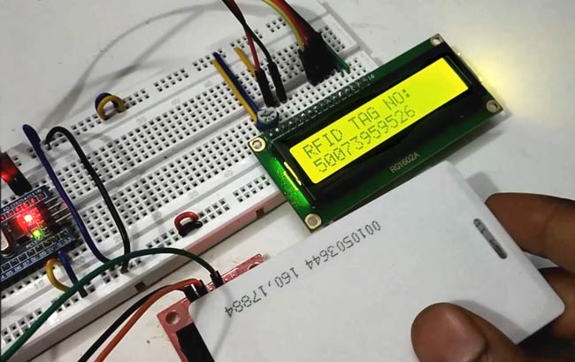
Complete code and Demonstration Video for using RFID with STM32 microcontroller are given below.
Complete Project Code
//Interfacing EM-18 RFID READER MODULE with STM32F103C8
//Circuit Digest
#include <LiquidCrystal.h>                                               //Library for using LCD display functions
const int rs = PB11, en = PB10, d4 = PB0, d5 = PB1, d6 = PC13, d7 = PC14; //mention the pin names to with LCD is connected to STM32F103C8
LiquidCrystal lcd(rs, en, d4, d5, d6, d7);                                //Initialize the LCD display
int count = 0;
char RFID[12];                                                             //Arrary for storing 12 characters of ID


void setup()
{
lcd.begin(16, 2);                  // setting LCD as 16x2 type
Serial1.begin(9600);               //begins serial communication at 9600 baud rate
pinMode(PA10,INPUT);               //Set PA10 as input pin from EM-18
lcd.print("CIRCUIT DIGEST");       //Prints at LCD display
lcd.setCursor(0, 1);               //Set courser to second line
lcd.print("RFID WITH STM32");      //Prints at LCD display
delay(5000);                       //Delay for 5 Seconds
 lcd.clear();                       //Clears LCD display
 lcd.setCursor(0,0);                //Sets cursor at First Line
 lcd.print("RFID TAG NO:");         //Prints at LCD display
 lcd.setCursor(0,1);                //Sets cursor at Second line
}


void loop()
{
while(Serial1.available() && count < 12)          // While loop to read 12 characters and store them in input array
{
RFID[count] = Serial1.read();                  //storing 12 characters one by one
    count++;
    lcd.print(RFID[count]);                         //showing 12 characters on LCD one by one

if (count==12)
    {
lcd.print("             ");
count = 0;                          // once 12 characters are read get to start and wait for second ID
lcd.setCursor(0, 1);                //move courser to start.
}
}
}

I am getting the error as - No debug probe detected.
I have connected the probe correctly then also i am getting the same again and again