
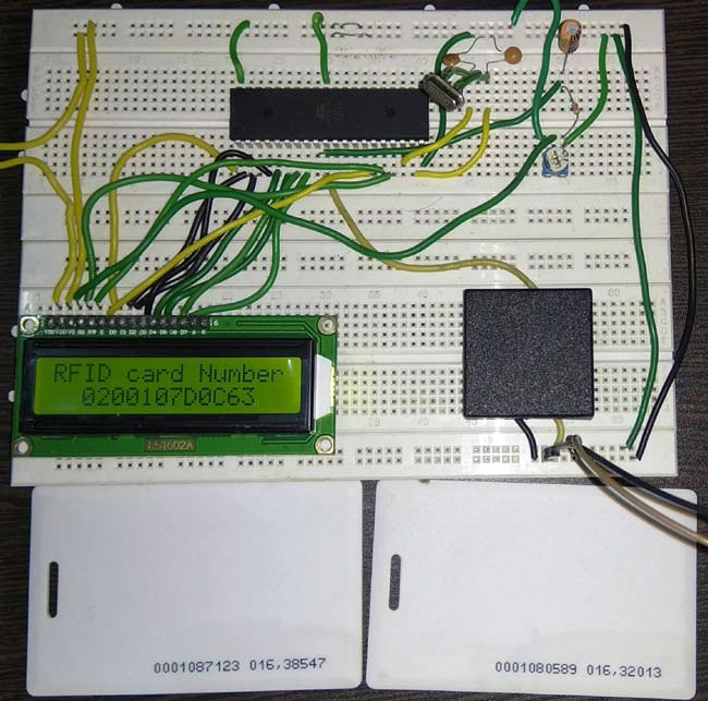
Radio Frequency Identification (RFID) uses radio frequency to read information stored in a RFID card or tag. In this project we are going to Interface EM-18 RFID reader with 8051 microcontroller and display RFID card number on 16*2 LCD display. This wireless RF Identification is used in many systems like RFID Based Attendance System, security systems, voting machines etc. This project will also serve as a proper interfacing of 16*2 LCD with 8051 microcontroller.
Components Required:
- 8051 microcontroller
- EM-18 RFID reader
- 16*2 LCD display
- RFID cards/tags
- Potentiometer
- Jumper wires
Circuit Diagram:

8051 Microcontroller:
8051 microcontroller is a 8 bit microcontroller which has 128 bytes of on chip RAM, 4K bytes of on chip ROM, two timers, one serial port and four 8bit ports. 8052 microcontroller is an extension of microcontroller. The table below shows the comparison of 8051 family members.
|
Feature |
8051 |
8052 |
|
ROM (in bytes) |
4K |
8K
|
|
RAM (bytes) |
128 |
256 |
|
Timers |
2 |
3 |
|
I/O pins |
32 |
32 |
|
Serial port |
1 |
1 |
|
Interrupt sources |
6 |
8 |
16x2 LCD:
16*2 LCD is a widely used display for embedded applications. Here is the brief explanation about pins and working of 16*2 LCD display. There are two very important registers inside the LCD. They are data register and command register. Command register is used to send commands such as clear display, cursor at home etc., data register is used to send data which is to be displayed on 16*2 LCD. Below table shows the pin description of 16*2 lcd.
|
Pin |
Symbol |
I/O |
Description |
|
1 |
Vss |
- |
Ground |
|
2 |
Vdd |
- |
+5V power supply |
|
3 |
Vee |
- |
Power supply to control contrast |
|
4 |
RS |
I |
RS=0 for command register , RS=1 for data register |
|
5 |
RW |
I |
R/W=0 for write , R/W=1 for read |
|
6 |
E |
I/O |
Enable |
|
7 |
D0 |
I/O |
8-bit data bus(LSB) |
|
8 |
D1 |
I/O |
8-bit data bus |
|
9 |
D2 |
I/O |
8-bit data bus |
|
10 |
D3 |
I/O |
8-bit data bus |
|
11 |
D4 |
I/O |
8-bit data bus |
|
12 |
D5 |
I/O |
8-bit data bus |
|
13 |
D6 |
I/O |
8-bit data bus |
|
14 |
D7 |
I/O |
8-bit data bus(MSB) |
|
15 |
A |
- |
+5V for backlight |
|
16 |
K |
- |
Ground |
The below table shows frequently used LCD command codes.
|
Code(hex) |
Description |
|
01 |
Clear display screen |
|
06 |
Increment cursor (right shift) |
|
0A |
Display off , cursor on |
|
0C |
Display on , cursor off |
|
0F |
Display on , cursor blinking |
|
80 |
Force the cursor to beginning of 1st line |
|
C0 |
Force the cursor to beginningof 2nd line |
|
38 |
2 lines and 5*7 matrix |
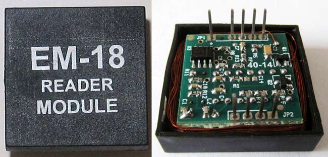
EM-18 RFID Reader:
EM-18 RFID reader operates at 125 KHz and it comes with an on-chip antenna and it can be powered with 5V power supply. It provides serial output along with weigand output. The range is around 8-12cm. serial communication parameters are 9600bps, 8 data bits, 1 stop bit. Its applications include Authentication, e-toll road pricing, e-ticketing for public transport, attendance systems etc. Check all the RFID Projects here.
The output provided by EM-18 RFID reader is in 12 digit ASCII format. Out of 12 digits first 10 digits are card number and the last two digits are the XOR result of the card number. Last two digits are used for error checking.

For example, card number is 0200107D0D62 read from the reader then the card number on the card will be as below.
02 – preamble
00107D0D = 1080589 in decimal.
62 is XOR value for (02 XOR 00 XOR 10 XOR 7D XOR 0D).
Hence number on the card is 0001080589.
Working and Code explanation:
The complete C program and demonstration Video for this project is given at the end of this project. The code is split into small meaningful chunks and explained below.
For 16*2 LCD interfacing with 8051 microcontroller, we have to define pins on which 16*2 lcd is connected to 8051 microcontroller. RS pin of 16*2 lcd is connected to P3.7, RW pin of 16*2 lcd is connected to P3.6 and E pin of 16*2 lcd is connected to P3.5. Data pins are connected to port 1 of 8051 microcontroller.
sbit rs=P3^7;
sbit rw=P3^6;
sbit en=P3^5;
Next we have to define some functions which are used in the program. Delay function is used to create specified time delay. Cmdwrt function is used to send commands to 16*2 lcd display. datawrt function is used to send data to 16*2 lcd display. Rxdata function is used to receive data from serial port.
void delay(unsigned int)  ;
void cmdwrt(unsigned char);
void datawrt(unsigned char);
char rxdata(void);
In this part of the code we are going to configure 8051 microcontroller for serial communication.
TMOD register is loaded with 0x20 for timer 1, mode 2 (auto reload). SCON register is loaded with 0x50 for 8 data bits, 1 stop bit and receive enabled. TH1 register is loaded with 0xfd for baud rate of 9600 bits per second. TR1=1 is used to start the timer.
TMOD= 0x20;
SCON=0x50;
TH1=0xfd;
TR1=1;
In this part of the code , we are sending commands to 16*2 lcd. Commands such as clear display , increment cursor , force the cursor to beginning of 1st line are sent to 16*2 lcd display one by one after some some specified time delay.
for(i=0;i<5;i++)
 {
         cmdwrt (cmd[i]);
         delay (1);
   }
In this part of the code we are receiving the output of the EM-18 RFID reader through serial interface of 8051 microcontroller and stored in a variable. Count is used to keep track of number of bytes received. Once all the 12bytes of data are received, next we have to display it on 16*2 lcd display. This process is repeated forever in order to read different cards.
while(1)
{
   count=0;
   cmdwrt(0xC2);
  while(count<12)
 {
    input[count]=rxdata();
    count++;
  }
  for(i=0;i<12;i++)
  {
     datawrt(input[i]);
     delay(1);
 }
delay(100);
}
In this part of the code, we are sending commands to 16*2 lcd display. The command is copied to port 1 of 8051 microcontroller. RS is made low for command write. RW is made low for write operation. High to low pulse is applied on enable (E) pin to start command write operation.
void cmdwrt (unsigned char x)
{
   P1=x;
   rs=0;
   rw=0;
   en=1;
   delay(1);
   en=0;
}
In this part of the code , we are sending data to 16*2 lcd display. The data is copied to port 1 of 8051 microcontroller. RS is made high for command write . RW is made low for write operation. High to low pulse is applied on enable(E) pin to start data write operation.
void datawrt (unsigned char y)
{
   P1=y;
   rs=1;
   rw=0;
   en=1;
   delay(1);
   en=0;
}
Also, check our all RFID projects with other microcontrollers.
Complete Project Code
/*this program is for interfacing RFID reader with 8051 microcontroller and to display card number on 16*2 lcd display*/

#include<reg51.h>

sbit rs=P3^7;             //Register Select(RS) pin of 16*2 lcd
sbit rw=P3^6;             //Read/Write(RW) pin of 16*2 lcd
sbit en=P3^5;             //Enable(E) pin of 16*2 lcd

char count = 0;            // count = 0
char input[12];           // character array of size 12
char ch;

void delay(unsigned int)  ;                   //function for creating delay
void cmdwrt(unsigned char);              //function for sending commands to 16*2 lcd display
void datawrt(unsigned char);             //function for sending data to 16*2 lcd display
char rxdata(void);                                //function for receiving a character through serial port of 8051
microcontroller

 void main(void)
 {
                   unsigned char cmd[]={0x38,0x01,0x06,0x0c,0x80};           //16*2 lcd initialization commands
unsigned char msg[]={"RFID card Number"};
unsigned char i;
TMOD=0x20;                  //timer 1 , mode 2 , auto reload
SCON=0x50;                   //8bit data , 1 stop bit , REN enabled
TH1=0xfd;                  //timer value for 9600 bits per second(bps)
                   TR1=1;    //start the timer

                  for(i=0;i<5;i++)     //send commands to 16*2 lcd display one command at a time
                 {
                         cmdwrt(cmd[i]);       //function call to send commands to 16*2 lcd display
                         delay(1);
                 }

                 for(i=0;i<16;i++)             //send data to 16*2 lcd display one character at a time
                {
                         datawrt(msg[i]);    //function call to display message on 16*2 lcd display
                        delay(1);
                }

                 while(1)
                 {
                          count=0;
                          cmdwrt(0xC2);
                         while(count<12)                //repeat for 12 times
                         {
                                    input[count]=rxdata(); //receive serial data and store it.
                                    count++;
                         }

                         for(i=0;i<12;i++)                               //send data to 16*2 lcd display one character at a time
                          {
                            datawrt(input[i]);                //function call to display rfid card number on 16*2 lcd display
                             delay(1);
                           }

                            delay(100);
                   }
}

void cmdwrt (unsigned char x)
{
   P1=x;  //send the command to Port 1 on which 16*2 lcd is connected
   rs=0;  //make RS = 0 for command
   rw=0;  //make RW = 0 for write operation
   en=1;  //send a HIGH to LOW pulse on Enable(E) pin to start commandwrite operation
   delay(1);
   en=0;
}

void datawrt (unsigned char y)
{
   P1=y; //send the data to Port 1 on which 16*2 lcd is connected
   rs=1; //make RS = 1 for command
   rw=0; //make RW = 0 for write operation
   en=1; //send a HIGH to LOW pulse on Enable(E) pin to start datawrite operation
   delay(1);
   en=0;
}

char rxdata()
{
  while(RI==0);   //wait till RI becomes HIGH
  RI=0;           //make RI low
  ch=SBUF;      //copy received data
  return ch;      //return the received data to main function.
}

void delay(unsigned int z)
{
  unsigned int p,q;
  for(p=0;p<z;p++)    //repeat for 'z' times
  {
    for(q=0;q<1375;q++);   //repeat for 1375 times
  }
}
Comments
O2- PREAMBLE is same for all rfid cards?

Good work. Very well explained..