

An RFID-based attendance system transforms the tedious task of manual attendance tracking into an automated, error-free process. What makes this project particularly exciting is how a few inexpensive components can replace expensive commercial systems, giving you complete control over features while learning valuable skills in embedded programming and circuit design.
In this comprehensive Arduino project, we'll guide you through building a complete RFID attendance system using Arduino that automatically detects check-ins and check-outs, displays real-time information on an LCD, and stores attendance logs with precise timestamps. Through our experience developing hundreds of electronics projects at CircuitDigest, we've designed this system to be both educational and practical - you'll master SPI and I2C communication, learn EEPROM data management, and create a professional-grade solution that can handle everything from office attendance to classroom management. By the end of this tutorial, you'll have a fully functional system that rivals commercial solutions costing hundreds of dollars.
RFID Attendance System using Arduino - Quick Overview
Build Time: 4-6 hours | Cost: $25-35 | Difficulty: Beginner-Intermediate
What You'll Learn: SPI/I2C communication, EEPROM storage, Real-time clock programming, RFID card management
Applications: Office attendance, Student tracking, Access control, Visitor management
Table of Contents
- Why Choose Arduino for RFID Attendance Systems?
- Features
- Components Required
- Circuit Diagram
- Step-by-Step Assembly Guide
- Arduino Code
- Adding Personal Data to RFID Cards
- Project Demonstration
- Frequently Asked Questions
- Troubleshooting Guide
- Applications
- Future Enhancements and Upgrades
- Other Projects using RFID Module
- Conclusion
Why Choose Arduino for RFID Attendance Systems?
This RFID-based attendance system using an Arduino project, offers superior reliability compared to commercial solutions. The Arduino platform provides cost-effective customisation, while the MFRC522 RFID module ensures accurate card detection. Our system features automatic check-in/check-out detection, real-time clock integration, and persistent data storage that remains intact even during power outages. More than that, what is more fun than building your attendance system and having it used daily by your colleagues or student friends? This is not only a simple DIY RFID attendance tracker, but also opens room to future enhancements like IoT integration, wireless attendance monitoring, and much more.
Arduino RFID Attendance System Features
This attendance system is designed to be highly adaptable, making it useful across schools, offices, events, and even industrial settings. For more advanced security applications, you might also want to explore our RFID door lock system using Arduino, which shares similar hardware components.
This simple DIY Arduino attendance system can track student and employee attendance, manage access to libraries or meeting rooms, and monitor visitor entries. In workshops, gyms, or community centers, it ensures accurate logging and helps with usage tracking. Industrial setups can benefit from features like shift monitoring, worker safety tracking, and contractor management. This contactless attendance system ensures hygiene compliance while providing accurate employee time tracking and student attendance monitoring capabilities.
At its core, the system offers automatic check-in/check-out detection, real-time timestamping using an RTC module, and reliable data storage even during power loss. A user-friendly LCD interface provides real-time updates, while advanced features like live people count, scrolling name display, RFID-based access control, and automatic log management make the system smart and efficient. It can be operated either via physical buttons or through the serial monitor for added flexibility.
Components Required for the RFID Attendance System
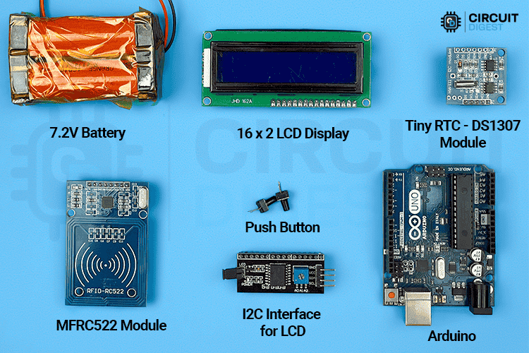
Arduino Uno (x1): Microcontroller board with ATmega328P, operates at 5V. Perfect for RFID-based projects and Arduino attendance tracking systems.
RFID Reader MFRC522 Module(x1): 13.56MHz RFID reader with SPI interface, supports read/write operations.
Tiny RTC DS1307 Module (x1): Real-time clock with I2C interface and CR2032 battery backup. It also has an AT24C32 EEPROM IC (32KB external memory module using I2C interface) in it.
16x2 I2C LCD Display (x1): HD44780-compatible character display with blue backlight and I2C backpack.
Push Buttons (x2): 6x6mm tactile buttons, normally open, used for user input.
RFID Cards/Tags (Required): Mifare Classic 1K, 13.56MHz, with 1KB memory for each card/tag.Breadboard (x1): Full-size breadboard for easy prototyping and circuit connections.
Jumper Wires (Required): Male-to-male and female connectors for wiring components.
Power Supply (x1): 5V–12V DC adapter for powering the Arduino, or in my case, we use 2S Lithium-ion battery connecting to the Vin pin.
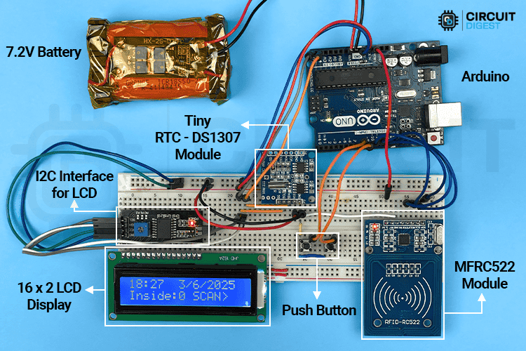
RFID Attendance System Circuit Diagram
Below you can see the circuit diagram used in the RFID attendance system project. If you are completely new to using RFID, you can check out this tutorial on interfacing RC522 RFID module with Arduino , where we explore the basics of RFID technology with Arduino and how it works with microcontrollers.

All components operate at 5V, with the Arduino providing regulated power to all modules. The I2C bus operates at 5V logic levels, while the RFID reader uses 3.3V internally but is 5V tolerant. The system employs multiple communication protocols to interface with various peripherals. The SPI (Serial Peripheral Interface) protocol is used exclusively for communicating with the MFRC522 RFID reader, ensuring high-speed data transfer.
The system utilises multiple I2C devices, each with a specific address for communication. The 16x2 I2C LCD display is assigned the address 0x27 and serves as the main output interface. The DS1307 Real-Time Clock (RTC) module, operating at address 0x68, keeps track of time, while the AT24C32 EEPROM module, addressed at 0x50, is used for data storage purposes.
For user interaction, simple digital I/O is used to read inputs from push buttons. Now let's see the detailed wiring connection used in the RFID attendance tracker system, starting from the Arduino UNO.
| Arduino Pin | Component | Function | Notes |
| Digital Pin 7 | MFRC522 RST | RFID Reset | Controls reader reset, Optional |
| Digital Pin 8 | Menu Button | Menu Navigation | INPUT_PULLUP enabled |
| Digital Pin 9 | Select Button | Selection/Confirm | INPUT_PULLUP enabled |
| Digital Pin 10 | MFRC522 SS | Slave Select | SPI chip select |
| Digital Pin 11 | MFRC522 MOSI | SPI Data Out | SPI communication |
| Digital Pin 12 | MFRC522 MISO | SPI Data In | SPI communication |
| Digital Pin 13 | MFRC522 SCK | SPI Clock | SPI communication |
| Analog Pin A4 | SDA | I2C Data | LCD, RTC, EEPROM |
| Analog Pin A5 | SCL | I2C Clock | LCD, RTC, EEPROM |
The MFRC522 RFID reader is connected to the Arduino Uno with VCC (3.3V) to 3.3V, GND to GND, RST to digital pin 7, SDA (SS) to digital pin 10, MOSI to pin 11, MISO to pin 12, and SCK to pin 13.
The DS1307 RTC module contains both the DS1307 and AT24C32 EEPROMs. So, connect both via I2C, with VCC to 5V, GND to GND, SDA to analog pin A4, and SCL to analog pin A5. The same applies to the I2C LCD.
Additionally, the user interface is equipped with two push buttons: a "Menu" button connected between digital pin 8 and GND, and a "Select" button connected between digital pin 9 and GND. Both buttons make use of internal pull-up resistors configured in the code.
Step-by-Step Arduino RFID System Assembly Guide
Step 1⇒Setup Breadboard
Place your Arduino next to the breadboard for easy access. Use a red wire to connect the Arduino's 5V pin to the breadboard's positive power rail, and a black wire to connect the Arduino's GND pin to the breadboard's negative power rail. This creates your main power distribution for all components.
Step 2 ⇒Connect the RFID Module
Plug the RFID module into the breadboard with enough space around it. Connect the VCC pin to the Arduino's 3.3V (not 5V), and GND to the ground rail. For the data connections, wire SDA to Pin 10, SCK to Pin 13, MOSI to Pin 11, MISO to Pin 12, and RST to Pin 9.
Step 3⇒Connect LCD Display
Wire your LCD display to the Arduino using the I2C connection. Connect VCC to the 5V power rail, GND to the ground rail, SDA to Pin A4, and SCL to Pin A5. The LCD should now share the same I2C bus that other devices will use.
Step 4⇒Connect the RTC Module
Connect the RTC module to the same I2C bus as the LCD. Wire VCC to the 5V power rail, GND to the ground rail, SDA to Pin A4 (same connection as LCD), and SCL to Pin A5 (same connection as LCD). Both devices can share these I2C lines.
Step 5⇒Add Buttons
Insert two push buttons on the breadboard in convenient locations. For each button, connect one terminal to the ground rail and the other terminal to a digital pin on the Arduino. Connect the first button to Pin 8 and the second button to Pin 7.
Step 6⇒Check Everything
Double-check all your connections against the circuit diagram. Make sure every component has proper power and ground connections, and that no wires are loose or touching each other. Connect the USB cable from your computer to the Arduino to provide power and programming capability.
Step 7⇒ Test
Upload a simple test program to verify all components are working. The LCD should display text, the RFID reader should detect cards, and the buttons should respond when pressed. If everything works, your assembly is complete and ready for the main program.
Remember: This assembly is suited for both updating the card data and running the main attendance logger program.
Arduino Code for RFID-Based Attendance System
The GitHub repository contains everything needed for the project, including the main attendance system code that manages RFID scanning, logging, and user feedback; a card programming utility to write and manage personal data like name and ID on RFID cards; and complete documentation with circuit diagrams to guide users through hardware setup and system integration.


Let’s begin with the Code,
Libraries and Dependencies
#include <SPI.h>
#include <MFRC522.h>
#include <Wire.h>
#include "RTClib.h"
#include <LiquidCrystal_I2C.h>
SPI: Handles communication with the RFID reader (Built-in Library)
MFRC522: Library for interfacing with the MFRC522 RFID module.
Wire: Supports I2C communication for RTC, EEPROM, and LCD. (Built-in Library)
RTClib: Manages the DS1307 Real-Time Clock module.
LiquidCrystal_I2C: Used to control a 16x2 LCD via I2C.
#define RST_PIN 7  // optional
#define SS_PIN 10
#define BUTTON_MENU 8
#define BUTTON_SELECT 9
Pin definitions establish the hardware connections, with RST_PIN and SS_PIN configured for RFID communication, and BUTTON_MENU and BUTTON_SELECT pins set up for user interface navigation.
#define EEPROM_ADDR 0x50
MFRC522 mfrc522(SS_PIN, RST_PIN);
RTC_DS1307 rtc;
LiquidCrystal_I2C lcd(0x27, 16, 2);
MFRC522::MIFARE_Key key;
Initialises objects for RFID, RTC, LCD, and the default RFID key.
#define NAME_START_BLOCK 4
#define ID_START_BLOCK 8
#define NAME_LENGTH 32
#define ID_LENGTH 8
#define MAX_LOGS 30
#define LOG_SIZE 80
int logCount = 0;
int insideCount = 0;
Data storage constants define the RFID card memory layout, with NAME_START_BLOCK and ID_START_BLOCK specifying where personal information is stored on cards.
Maximum lengths for names and IDs are set, along with log storage parameters including MAX_LOGS for total entries and LOG_SIZE for individual record size. These are customizable.
System state variables track the current number of stored logs, people currently inside the facility, and various timing and navigation states.
These values are customizable, but must be updated in both the main and personal data utility code for consistency.
enum MenuState {
 MENU_HOME,
 MENU_VIEW_LOGS,
 MENU_STATUS,
 MENU_CLEAR_LOGS,
 MENU_SET_TIME
};
MenuState currentMenu = MENU_HOME;
int menuIndex = 0;
unsigned long lastButtonPress = 0;
unsigned long lastLCDUpdate = 0;
unsigned long homeScreenTimer = 0;
bool inSubMenu = false;
int logViewIndex = 0;
unsigned long lastScrollTime = 0;
int scrollPosition = 0;
String currentScrollText = "";
bool isScrolling = false;
#define SCROLL_DELAY 500
#define SCROLL_PAUSE 2000
bool menuButtonPressed = false;
bool selectButtonPressed = false;
The MenuState enumeration defines different screen modes, including home display, log viewing, status checking, log clearing, and time setting. Navigation variables manage menu indexing, button debouncing, LCD update timing, and scrolling text animation parameters.
The setup function runs once when the Arduino powers on and gets everything ready to work.
Serial.begin(9600);
 pinMode(BUTTON_MENU, INPUT_PULLUP);
 pinMode(BUTTON_SELECT, INPUT_PULLUP);
It starts serial communication so you can see debug messages on your computer, then configures the button pins to use internal pull-up resistors. This means the buttons read as HIGH normally and LOW when pressed.
lcd.begin();
 lcd.backlight();
 lcd.clear();
 lcd.setCursor(0, 0);
 lcd.print("RFID Attendance");
 lcd.setCursor(0, 1);
 lcd.print("Starting up...");
 delay(2000);
 SPI.begin();
 mfrc522.PCD_Init();
 Wire.begin();
The LCD display gets initialised and shows a startup message while other components are being prepared. The system starts SPI communication for the RFID reader, initialises the RFID module itself, and begins I2C communication for the clock and memory chip.
if (!rtc.begin()) {
   lcd.clear();
   lcd.setCursor(0, 0);
   lcd.print("RTC Error!");
   Serial.println(F("RTC Error!"));
   while(1);  // Stop execution if RTC fails
 }
 for (byte i = 0; i < 6; i++) {
   key.keyByte[i] = 0xFF;
 }
One critical check happens here - if the real-time clock doesn't respond properly, the system stops completely. This makes sense because accurate timestamps are essential for an attendance system. The RFID security key gets set to the default values that work with most MIFARE cards.
logCount = readInt(0); // Read log count from address 0
insideCount = readInt(2); // Read inside count from address 2
if (logCount < 0 || logCount > MAX_LOGS) logCount = 0;
if (insideCount < 0) insideCount = 0;
lcd.clear();
lcd.setCursor(0, 0);
lcd.print("System Ready!");
lcd.setCursor(0, 1);
lcd.print("Inside: ");
lcd.print(insideCount);
delay(2000);
Serial.println(F("\n=== RFID IN/OUT System Ready ==="));
Serial.print(F("Total logs: "));
Serial.println(logCount);
Serial.print(F("People inside: "));
Serial.println(insideCount);
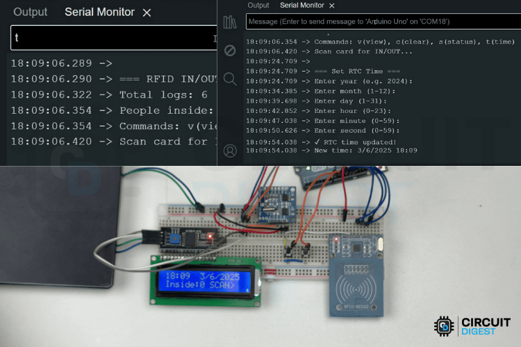
Serial.println(F("Commands: v(view), c(clear), s(status), t(time)"));
Serial.println(F("Scan card for IN/OUT..."));
displayHomeScreen();The system then reads saved data from the external memory chip, including how many log entries exist and how many people are currently inside. If these numbers seem wrong (negative or too large), they get reset to safe values. Finally, the LCD shows a "System Ready" message along with the current inside count, and the home screen appears.
void loop() {
 handleButtons();
 handleSerialCommands();
 handleLCDUpdates();
 handleRFIDScan();
 handleScrolling();
}
handleButtons(): Checks for button presses with debouncing.
handleSerialCommands(): Allows users to type commands like view, clear, or status through the Serial Monitor.
handleLCDUpdates(): Refreshes the display and handles timeouts.
handleRFIDScan(): Continuously scans for cards and updates logs.
handleScrolling(): Animates text for names or IDs longer than 16 characters.
With this, the coding part is complete. Let's move on to the demonstration.
Adding Personal Data to RFID Cards
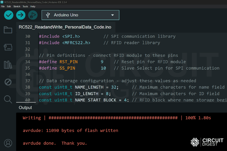
To test the system, we first need to load RFID cards with individual names and IDs. This is done using the ReadandWrite_PersonalData.ino sketch.
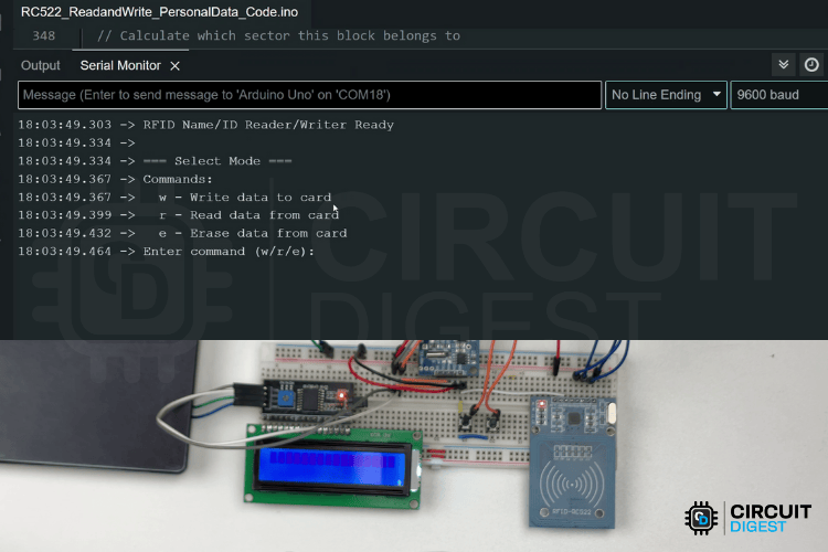
1. Open Serial Monitor (9600 baud)
2. Select Write Mode and Place Card, and Enter Data:
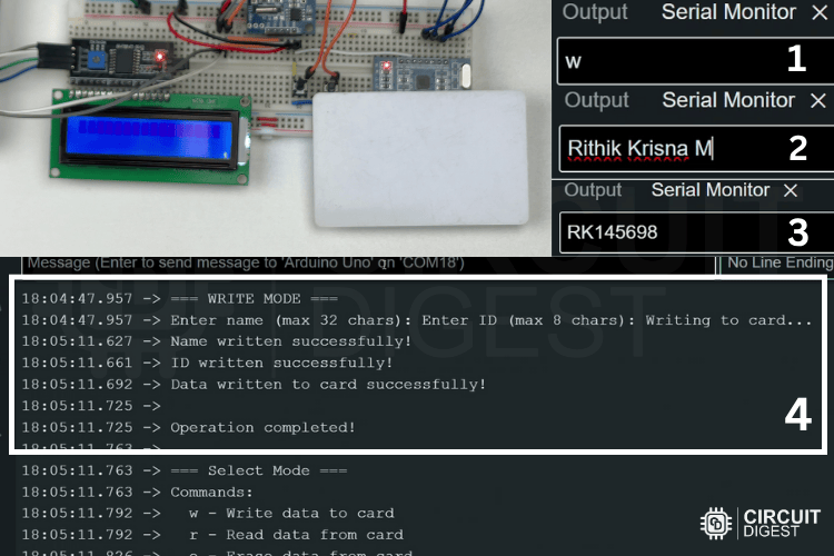
Type 'w' and press Enter
System prompts: "WRITE mode selected. Place card near the reader..."
Position the RFID card near the reader
Enter name when prompted (max 32 characters)
Enter ID when prompted (max 8 characters)
System confirms successful write
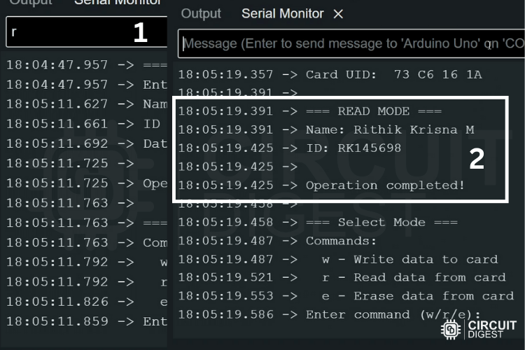
3. Verify Card Data:
Type 'r' for read mode
Place the same card near the reader
Verify stored name and ID are correct
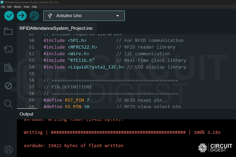
Now let us upload the Main code(RFIDAttendanceSystem_Main.ino) and check the Attendance logging functionality
RFID-based Attendance System Demonstration
After successfully uploading of main code, you can see the system starts working,
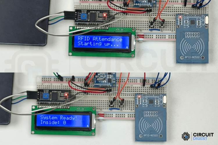
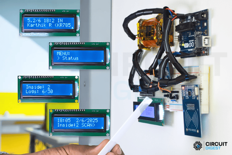
When the system is powered on, it displays the "RFID Attendance" startup message, initializes all hardware components, loads stored data from the EEPROM (such as log count and inside count), and shows the home screen with the current time and inside count.
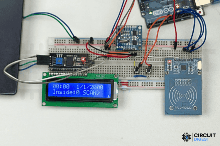
The home screen displays the current time (HH: MM) and date (DD/MM/YYYY) on the top line, and the inside count along with the "SCAN>" prompt on the bottom line, updating automatically every 30 seconds.
When a valid RFID card is scanned, the system shows a "Scanning card..." message, reads the stored name and ID from the card, validates the data (ensuring both name and ID are present), determines the new status based on the last recorded status, updates the inside count (adding 1 for IN or subtracting 1 for OUT), logs the entry with a timestamp to the EEPROM, displays the result for 3 seconds, and then returns to the home screen.
Before using the system, you must set the correct time on the RTC (Real-Time Clock). This can be done easily via the Serial Monitor, as you can see in the image below.
RFID Attendance System Project Demonstration
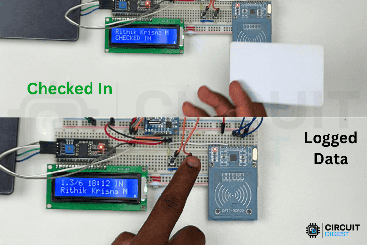
Scenario 1: Morning Check-in
» Employee arrives at the office
» Presents the RFID card to the reader
» System shows "Rithik Krisna M CHECKED IN"
» Inside count increases from 0 to 1
» Log entry created with timestamp
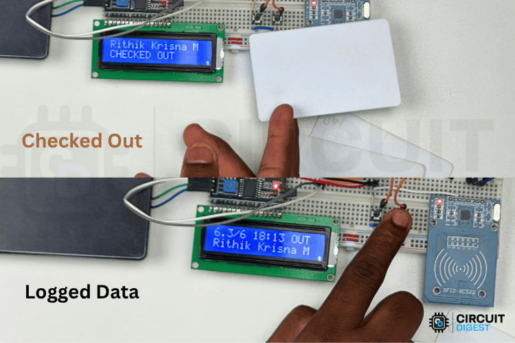
Scenario 2: Lunch Break
» Same employee scans the card before lunch
» System shows "Rithik Krisna M CHECKED OUT"
» Inside count decreases from 1 to 0
» New log entry shows OUT status
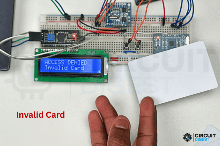
Scenario 3: Invalid Card
» Uninitialized card is presented
» System shows 'ACCESS DENIED - Invalid Card"
» No log entry is created
» Inside count remains unchanged
This RFID-based attendance System provides a robust, scalable solution for automated attendance tracking. With proper assembly and configuration, it offers reliable operation suitable for various professional and educational environments. The modular design allows for easy customisation and expansion to meet specific requirements.
For updates, additional features, and community support, visit the project's GitHub repository and Arduino community forums.
Frequently Asked Questions - RFID Attendance System
⇥ How does an RFID-based attendance system using Arduino work?
An RFID-based attendance system using Arduino works by detecting RFID cards when they're brought near the MFRC522 reader. The Arduino reads the card's unique ID, checks if it contains valid employee/student data, determines whether it's a check-in or check-out based on the last recorded status, logs the entry with a timestamp from the RTC module, and displays the result on the LCD screen while updating the people count.
⇥ What is the cost of building an Arduino RFID attendance system?
The total cost for building this RFID attendance system using Arduino is approximately $25-35, including Arduino Uno ($15), MFRC522 RFID module ($5), RTC module ($3), I2C LCD ($5), RFID cards ($2), and supporting components ($5). This is significantly cheaper than commercial solutions that cost $200-500.
⇥ Can this Arduino RFID system work without an internet connection?
Yes, this RFID-based attendance system using Arduino works completely offline. All attendance data is stored locally in the AT24C32 EEPROM module, and the DS1307 RTC maintains accurate timestamps even during power outages. No internet connection or external database is required for operation.
⇥ How many people can this Arduino attendance system handle?
The current system can store up to 30 attendance logs and unlimited RFID cards. Each log entry contains name, ID, timestamp, and status. The system can be easily modified to increase storage capacity by using larger EEPROM modules or adding SD card storage for handling hundreds of users.
⇥ What are the advantages of Arduino over commercial attendance systems?
Building an RFID attendance system using Arduino offers complete customisation, lower cost (90% cheaper), no monthly fees, offline operation, easy maintenance, and the ability to add features like access control, visitor management, or integration with existing systems. You also learn valuable programming and electronics skills.
Arduino RFID Attendance System Troubleshooting Guide
1. LCD Display Problems
Issue: LCD shows garbled text or remains blank
Solutions:
Check I2C connections (A4 = SDA, A5 = SCL)
Verify LCD I2C address (default 0x27, may be 0x3F)
Check power connections (5V and GND)
Run the I2C scanner code to detect the LCD address
Adjust the contrast potentiometer on the LCD backpack
Issue: LCD backlight works, but no text
Solutions:
Verify that the I2C address in the code matches the physical address
Check soldering on the I2C backpack
Test with a simple "Hello World" LCD sketch
2. RFID Reader Issues
Issue: Cards not detected
Solutions:
Check SPI wiring (MOSI=11, MISO=12, SCK=13, SS=10, RST=7)
Verify 3.3V/5V compatibility (MFRC522 is 3.3V but 5V tolerant)
Try different RFID cards (some cards may be incompatible)
Check the antenna connection on the RFID module
Reduce the distance between the card and the reader
Issue: "Authentication failed" errors
Solutions:
Cards may have modified security keys
Use fresh/new RFID cards with default keys
Verify card type (Mifare Classic 1K recommended)
Check if cards are write-protected
3. RTC Module Problems
Issue: Time resets on power cycle
Solutions:
Check the CR2032 battery in the RTC module
Replace the battery if the voltage < 2.5V
Verify RTC module connections
Set time using the serial command 't'
Issue: RTC not found error
Solutions:
Check I2C connections
Verify the RTC module is DS1307 compatible
Run the I2C scanner to detect the RTC at address 0x68
Check for loose connections
4. EEPROM Storage Issues
Issue: Logs not saved between power cycles
Solutions:
Verify EEPROM connections (I2C)
Check EEPROM address (0x50)
Test EEPROM with a simple read/write sketch
Some RTC modules include AT24C32 EEPROM
5. Button Response Problems
Issue: Buttons not responding or multiple triggers
Solutions:
Check button connections (pin to GND when pressed)
Verify the INPUT_PULLUP configuration in the code
Add hardware debouncing capacitors (100nF)
Increase software debounce delay
Check for loose connections
6. Power Supply Issues
Issue: System resets or behaves erratically
Solutions:
Use an adequate power supply (2A recommended)
Check all ground connections
Add decoupling capacitors near power pins
Use a powered USB hub instead of computer's USB
Check for short circuits
7. Serial Communication Problems
Issue: No serial output or garbled characters
Solutions:
Verify baud rate (9600)
Check the USB cable and connection
Try a different USB port
Reset Arduino and reconnect
Check if another program is using the serial port
Real-World Applications of Arduino RFID Attendance System
Educational Institutions: Schools and colleges can use this RFID attendance system using Arduino for automatic student attendance, library access control, and hostel entry management. The system eliminates proxy attendance and provides accurate data for academic records.
Corporate Offices: Offices can implement this system for employee time tracking, meeting room access, and visitor management. The offline capability ensures continuous operation even during network outages, making it ideal for small to medium-sized businesses.
Healthcare Facilities: Hospitals and clinics can track staff attendance, monitor restricted area access, and maintain visitor logs. The system's hygienless operation (no physical contact) makes it perfect for healthcare environments.
Industrial and Manufacturing: Manufacturing units can use this Arduino RFID system for shift management, safety compliance tracking, and contractor access control. The rugged design withstands industrial environments.
Future Enhancements and Upgrades
This RFID attendance system using Arduino can be enhanced with additional features:
∗ WiFi Connectivity: Add ESP8266 for remote monitoring and cloud backup
∗ Mobile App: Develop a smartphone app for real-time attendance viewing
∗ Biometric Integration: Combine with a fingerprint sensor for dual authentication
∗ Photo Capture: Add a camera module for visual attendance verification
∗ Database Integration: Connect to MySQL or MongoDB for advanced analytics
∗ Multi-location Support: Network multiple units for campus-wide deployment
∗ Access Control: Add relay control for automatic door locking/unlocking
Projects using the RFID Module
Previously, we have used this RFID module to build many interesting RFID projects. If you want to know more about those topics, links are given below.

How to Make an RFID Door Lock System using Arduino?
Build your own RFID door lock system using Arduino and the MFRC522 module. Enhance security with RFID-based access control and a real-time locking mechanism, ideal for homes, offices, and labs.

IoT-based Event Management System using RFID and ThingSpeak
Build an IoT-based event management system using NodeMCU and RFID to automate guest check-in, attendance tracking, and real-time data updates. Ideal for smart event solutions.

How to Connect RFID with STM32 Microcontroller
Learn how to interface an RFID reader with an STM32 microcontroller to read RFID card data. Ideal for authentication systems, automated tolls, hospital records, and more.
Conclusion
This comprehensive guide demonstrates how to build a professional RFID-based attendance system using Arduino from scratch. With components costing under $35, you've created a system that rivals commercial solutions costing hundreds of dollars. The combination of Arduino's flexibility, RFID technology's reliability, and your programming skills results in a fully customizable attendance tracking solution perfect for schools, offices, and industrial applications.
Whether you're a student learning embedded systems, a teacher looking for classroom projects, or a professional implementing cost-effective solutions, this Arduino RFID attendance system provides the foundation for countless possibilities. From basic attendance logging to advanced features like access control and visitor management, the modular design ensures easy expansion and customisation. If you have any questions related to this project, you can post them in the comment section below or use the Ask Our Community option to start a discussion with our 100K+ registered users.
Complete Project Code
/* RFID Card Reader/Writer with Mode Selection
* AUTHOR: CircuitDigest/me_RK
* VERSION: 1.0
*/
#include <SPI.h>         // SPI communication library
#include <MFRC522.h>     // RFID reader library
// Pin definitions - connect RFID module to these pins
#define RST_PIN         9    // Reset pin for RFID module
#define SS_PIN          10   // Slave Select pin for SPI communication
// Data storage configuration - adjust these values as needed
const uint8_t NAME_LENGTH = 32;     // Maximum characters for name field
const uint8_t ID_LENGTH = 8;        // Maximum characters for ID field
const uint8_t NAME_START_BLOCK = 4; // RFID block where name storage begins
const uint8_t ID_START_BLOCK = 8;   // RFID block where ID storage begins
// Calculate how many RFID blocks needed (each block holds 16 bytes)
const uint8_t NAME_BLOCKS = (NAME_LENGTH + 15) / 16; // 2 blocks for 32 chars
const uint8_t ID_BLOCKS = (ID_LENGTH + 15) / 16;     // 1 block for 8 chars
// Create RFID reader object
MFRC522 mfrc522(SS_PIN, RST_PIN);
// Default authentication key for RFID cards (all cards start with this key)
MFRC522::MIFARE_Key key;
// Global variable to store selected operation mode
char selectedMode = '\0';  // '\0' means no mode selected
void setup() {
 // Initialize serial communication for user interaction
 Serial.begin(9600);
 while (!Serial);  // Wait for serial port to connect

 // Initialize SPI bus and RFID reader
 SPI.begin();
 mfrc522.PCD_Init();

 // Set up default authentication key (FF FF FF FF FF FF)
 for (byte i = 0; i < 6; i++) {
   key.keyByte[i] = 0xFF;
 }

 // Display startup message and show available commands
 Serial.println("RFID Name/ID Reader/Writer Ready");
 promptForMode();
}
void loop() {
 // STEP 1: Check if user has selected a mode
 if (selectedMode == '\0') {
   // No mode selected - wait for user to choose operation
   if (Serial.available() > 0) {
     char command = Serial.read();

     // Clear any extra characters from serial buffer
     while (Serial.available() > 0) {
       Serial.read();
     }

     // Process user's command
     switch (command) {
       case 'w':
       case 'W':
         selectedMode = 'w';  // Set write mode
         Serial.println("WRITE mode selected. Now place your card near the reader...");
         break;
       case 'r':
       case 'R':
         selectedMode = 'r';  // Set read mode
         Serial.println("READ mode selected. Now place your card near the reader...");
         break;
       case 'e':
       case 'E':
         selectedMode = 'e';  // Set erase mode
         Serial.println("ERASE mode selected. Now place your card near the reader...");
         break;
       default:
         // Invalid command entered
         Serial.println("Invalid command. Please enter 'w' for write, 'r' for read, or 'e' for erase.");
         break;
     }
   }
   return; // Don't scan for cards until mode is selected
 }

 // STEP 2: Mode is selected - now scan for RFID cards
 if (!mfrc522.PICC_IsNewCardPresent()) {
   return;  // No card detected, keep waiting
 }
 // STEP 3: Select and read the detected card
 if (!mfrc522.PICC_ReadCardSerial()) {
   return;  // Failed to read card, try again
 }
 // STEP 4: Card successfully detected - show card information
 Serial.println("\nCard detected!");
 Serial.print("Card UID: ");
 printHex(mfrc522.uid.uidByte, mfrc522.uid.size);  // Display unique card ID
 Serial.println();
 // STEP 5: Execute the operation based on selected mode
 switch (selectedMode) {
   case 'w':
     writeCardData();   // Write name and ID to card
     break;
   case 'r':
     readCardData();    // Read name and ID from card
     break;
   case 'e':
     eraseCardData();   // Erase data from card
     break;
 }
 // STEP 6: Clean up after operation
 mfrc522.PICC_HaltA();         // Stop communication with card
 mfrc522.PCD_StopCrypto1();    // Stop encryption

 // STEP 7: Reset system for next operation
 selectedMode = '\0';           // Clear selected mode
 Serial.println("\nOperation completed!");
 promptForMode();               // Ask user to select next operation
}
// Function to display available commands to user
void promptForMode() {
 Serial.println("\n=== Select Mode ===");
 Serial.println("Commands:");
 Serial.println("  w - Write data to card");
 Serial.println("  r - Read data from card");
 Serial.println("  e - Erase data from card");
 Serial.print("Enter command (w/r/e): ");
}
// Function to write name and ID data to RFID card
void writeCardData() {
 String name, id;  // Variables to store user input

 Serial.println("\n=== WRITE MODE ===");

 // Get name from user
 Serial.print("Enter name (max " + String(NAME_LENGTH) + " chars): ");
 while (Serial.available() == 0) {}  // Wait for user input
 name = Serial.readStringUntil('\n');
 name.trim();  // Remove extra spaces

 // Get ID from user
 Serial.print("Enter ID (max " + String(ID_LENGTH) + " chars): ");
 while (Serial.available() == 0) {}  // Wait for user input
 id = Serial.readStringUntil('\n');
 id.trim();  // Remove extra spaces

 // Check if inputs are not too long
 if (name.length() > NAME_LENGTH) {
   Serial.println("Error: Name too long!");
   return;
 }

 if (id.length() > ID_LENGTH) {
   Serial.println("Error: ID too long!");
   return;
 }

 Serial.println("Writing to card...");

 // Write name to card blocks
 if (writeStringToBlocks(name, NAME_START_BLOCK, NAME_BLOCKS, NAME_LENGTH)) {
   Serial.println("Name written successfully!");
 } else {
   Serial.println("Failed to write name!");
   return;
 }

 // Write ID to card blocks
 if (writeStringToBlocks(id, ID_START_BLOCK, ID_BLOCKS, ID_LENGTH)) {
   Serial.println("ID written successfully!");
 } else {
   Serial.println("Failed to write ID!");
   return;
 }

 Serial.println("Data written to card successfully!");
}
// Function to read name and ID data from RFID card
void readCardData() {
 Serial.println("\n=== READ MODE ===");

 // Read name from card blocks
 String name = readStringFromBlocks(NAME_START_BLOCK, NAME_BLOCKS, NAME_LENGTH);
 if (name != "") {
   Serial.println("Name: " + name);
 } else {
   Serial.println("Failed to read name!");
 }

 // Read ID from card blocks
 String id = readStringFromBlocks(ID_START_BLOCK, ID_BLOCKS, ID_LENGTH);
 if (id != "") {
   Serial.println("ID: " + id);
 } else {
   Serial.println("Failed to read ID!");
 }
}
// Function to erase all data from RFID card
void eraseCardData() {
 Serial.println("\n=== ERASE MODE ===");

 // Create empty strings to overwrite existing data
 String emptyName = "";
 String emptyId = "";

 Serial.println("Erasing card data...");

 // Overwrite name blocks with empty data
 if (writeStringToBlocks(emptyName, NAME_START_BLOCK, NAME_BLOCKS, NAME_LENGTH)) {
   Serial.println("Name erased successfully!");
 } else {
   Serial.println("Failed to erase name!");
   return;
 }

 // Overwrite ID blocks with empty data
 if (writeStringToBlocks(emptyId, ID_START_BLOCK, ID_BLOCKS, ID_LENGTH)) {
   Serial.println("ID erased successfully!");
 } else {
   Serial.println("Failed to erase ID!");
   return;
 }

 Serial.println("Card data erased successfully!");
}
// Function to write string data to multiple RFID blocks
bool writeStringToBlocks(String data, uint8_t startBlock, uint8_t numBlocks, uint8_t maxLength) {
 // Pad string with null characters to fill the allocated space
 while (data.length() < maxLength) {
   data += '\0';
 }

 // Write data block by block (each block holds 16 bytes)
 for (uint8_t i = 0; i < numBlocks; i++) {
   uint8_t block = startBlock + i;

   // Skip trailer blocks (they contain authentication keys, not data)
   if ((block + 1) % 4 == 0) {
     Serial.println("Skipping trailer block " + String(block));
     continue;
   }

   // Prepare 16-byte buffer for this block
   byte buffer[16];
   for (int j = 0; j < 16; j++) {
     int charIndex = i * 16 + j;  // Calculate position in string
     if (charIndex < data.length()) {
       buffer[j] = data.charAt(charIndex);  // Copy character
     } else {
       buffer[j] = 0;  // Fill remaining space with zeros
     }
   }

   // Authenticate before writing (required for security)
   if (!authenticateBlock(block)) {
     return false;
   }

   // Write the 16-byte buffer to the block
   MFRC522::StatusCode status = mfrc522.MIFARE_Write(block, buffer, 16);
   if (status != MFRC522::STATUS_OK) {
     Serial.println("Write failed for block " + String(block) + ": " + String(mfrc522.GetStatusCodeName(status)));
     return false;
   }
 }

 return true;  // All blocks written successfully
}
// Function to read string data from multiple RFID blocks
String readStringFromBlocks(uint8_t startBlock, uint8_t numBlocks, uint8_t maxLength) {
 String result = "";  // String to store the read data

 // Read data block by block
 for (uint8_t i = 0; i < numBlocks; i++) {
   uint8_t block = startBlock + i;

   // Skip trailer blocks (they don't contain our data)
   if ((block + 1) % 4 == 0) {
     continue;
   }

   // Authenticate before reading (required for security)
   if (!authenticateBlock(block)) {
     return "";  // Authentication failed
   }

   // Read 16 bytes from the block
   byte buffer[18];  // Extra bytes for safety
   byte size = sizeof(buffer);
   MFRC522::StatusCode status = mfrc522.MIFARE_Read(block, buffer, &size);

   if (status != MFRC522::STATUS_OK) {
     Serial.println("Read failed for block " + String(block) + ": " + String(mfrc522.GetStatusCodeName(status)));
     return "";
   }

   // Convert bytes to string (16 bytes per block)
   for (int j = 0; j < 16; j++) {
     if (result.length() >= maxLength) break;  // Don't exceed max length
     if (buffer[j] != 0) {  // Only add non-null characters
       result += (char)buffer[j];
     }
   }
 }

 return result;
}
// Function to authenticate access to a specific block
bool authenticateBlock(uint8_t block) {
 // Calculate which sector this block belongs to
 uint8_t sector = block / 4;  // Each sector has 4 blocks
 uint8_t trailerBlock = sector * 4 + 3;  // Last block of sector contains keys

 // Authenticate using key A (default key)
 MFRC522::StatusCode status = mfrc522.PCD_Authenticate(
   MFRC522::PICC_CMD_MF_AUTH_KEY_A,  // Use key A
   trailerBlock,                      // Authenticate to sector's trailer block
   &key,                             // Authentication key
   &(mfrc522.uid)                    // Card's unique ID
 );

 if (status != MFRC522::STATUS_OK) {
   Serial.println("Authentication failed for sector " + String(sector) + ": " + String(mfrc522.GetStatusCodeName(status)));
   return false;
 }

 return true;  // Authentication successful
}
// Function to display bytes in hexadecimal format (for showing card UID)
void printHex(byte *buffer, byte bufferSize) {
 for (byte i = 0; i < bufferSize; i++) {
   Serial.print(buffer[i] < 0x10 ? " 0" : " ");  // Add leading zero if needed
   Serial.print(buffer[i], HEX);  // Print in hexadecimal
 }
}
// Utility function to change configuration at runtime (for advanced users)
void updateConfig(uint8_t nameLen, uint8_t idLen, uint8_t nameBlock, uint8_t idBlock) {
 // Note: Configuration variables are const, so this function is for reference only
 Serial.println("Configuration updated:");
 Serial.println("Name Length: " + String(nameLen));
 Serial.println("ID Length: " + String(idLen));
 Serial.println("Name Start Block: " + String(nameBlock));
 Serial.println("ID Start Block: " + String(idBlock));
}
