

Raspberry Pi is an ARM architecture processor based board designed for electronic engineers and hobbyists. The PI is one of most trusted project development platforms out there now. With higher processor speed and 1 GB RAM, the PI can be used for many high profile projects like Image processing and IoT.
For doing any of high profile projects, one need to understand the basic functions of PI. We will be covering all the basic functionalities of Raspberry Pi in these tutorials. In each tutorial we will discuss one of functions of PI. By the end of this Raspberry Pi Tutorial Series, you will be able to do high profile projects by yourself. Go through below tutorials:
- Getting Started with Raspberry Pi
- Raspberry Pi Configuration
- LED Blinky
- Button Interfacing
- PWM generation
- Controlling DC Motor
- Stepper Motor Control
- Interfacing Shift Register
- Raspberry Pi ADC Tutorial
- Servo Motor Control
- Capacitive Touch Pad
In this tutorial, we will Control a 16x2 LCD Display using Raspberry Pi. We will connect the LCD to GPIO (General Purpose Input Output) pins of PI to display characters on it. We will write a program in PYTHON to send the appropriate commands to the LCD through GPIO and display the needed characters on its screen. This screen will come in handy to display sensor values, interrupt status and also for displaying time.
There are different types of LCDs in the market. Graphic LCD is more complex than 16x2 LCD. So here we are going for 16x2 LCD display, you can even use 16x1 LCD if you want. 16x2 LCD has 32 characters in total, 16 in 1st line and another 16 in 2nd line. JHD162 is 16x2 LCD Module characters LCD. We have already interfaced 16x2 LCD with 8051, AVR, Arduino etc. You can find all our 16x2 LCD related project by following this link.
We will discuss a bit about PI GPIO before going any further.
There are 40 GPIO output pins in Raspberry Pi 2. But out of 40, only 26 GPIO pins (GPIO2 to GPIO27) can be programmed. Some of these pins perform some special functions. With special GPIO put aside, we have 17 GPIO remaining.
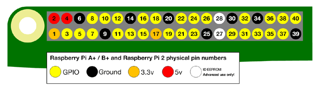
There are +5V (Pin 2 or 4) and +3.3V (Pin 1 or 17) power output pins on the board, these are for connecting other modules and sensors. We are going to power the 16*2 LCD through the +5V rail. We can send control signal of +3.3v to LCD but for working of LCD we need to power it by +5V. The LCD will not work with +3.3V.
To know more about GPIO pins and their current outputs, go through: LED Blinking with Raspberry Pi
Components Required:
Here we are using Raspberry Pi 2 Model B with Raspbian Jessie OS. All the basic Hardware and Software requirements are previously discussed, you can look it up in the Raspberry Pi Introduction, other than that we need:
- Connecting pins
- 16*2 LCD Module
- 1KΩresistor (2 pieces)
- 10K pot
- 1000µF capacitor
- Breadboard
Circuit and Working Explanation:

As shown in the Circuit Diagram, we have Interfaced Raspberry Pi with LCD display by connecting 10 GPIO pins of PI to the 16*2 LCD’s Control and Data Transfer Pins. We have used GPIO Pin 21, 20, 16, 12, 25, 24, 23, and 18 as a BYTE and created ‘PORT’ function to send data to LCD. Here GPIO 21 is LSB (Least Significant Bit) and GPIO18 is MSB (Most Significant Bit).
16x2 LCD Module has 16 pins, which can be divided into five categories, Power Pins, contrast pin, Control Pins, Data pins and Backlight pins. Here is the brief description about them:
Category | Pin NO. | Pin Name | Function |
Power Pins | 1 | VSS | Ground Pin, connected to Ground |
2 | VDD or Vcc | Voltage Pin +5V | |
Contrast Pin | 3 | V0 or VEE | Contrast Setting, connected to Vcc thorough a variable resistor. |
Control Pins | 4 | RS | Register Select Pin, RS=0 Command mode, RS=1 Data mode |
5 | RW | Read/ Write pin, RW=0 Write mode, RW=1 Read mode | |
6 | E | Enable, a high to low pulse need to enable the LCD | |
Data Pins | 7-14 | D0-D7 | Data Pins, Stores the Data to be displayed on LCD or the command instructions |
Backlight Pins | 15 | LED+ or A | To power the Backlight +5V |
16 | LED- or K | Backlight Ground |
We strongly recommend to just go through this article to understand the LCD working with its Pins and Hex Commands.
We will discuss briefly the process of sending data to LCD:
1. E is set high (enabling the module) and RS is set low (telling LCD we are giving command)
2. Giving value 0x01 to data port as a command to clear screen.
3. E is set high (enabling the module) and RS is set high (telling LCD we are giving data)
4. Proving the ASCII code for characters need to be displayed.
5. E is set low (telling LCD that we are done sending data)
6. Once this E pin goes low, the LCD process the received data and shows the corresponding result. So this pin is set to high before sending data and pulled down to ground after sending data.
As said we are going to send the characters one after the other. The characters are given to LCD by ASCII codes (American standard Code for Information Interchange). The table of ASCII codes is shown below. For example, to show a character “@”, we need to send a hexadecimal code “40”. If we give value 0x73 to the LCD it will display “s”. Like this we are going to send the appropriate codes to the LCD to display the string “CIRCUITDIGEST”.
Programming Explanation:
Once everything is connected as per the circuit diagram, we can turn ON the PI to write the program in PYHTON.
We will talk about few commands which we are going to use in PYHTON program,
We are going to import GPIO file from library, below function enables us to program GPIO pins of PI. We are also renaming “GPIO” to “IO”, so in the program whenever we want to refer to GPIO pins we will use the word ‘IO’.
import RPi.GPIO as IO
Sometimes, when the GPIO pins, which we are trying to use, might be doing some other functions. In that case, we will receive warnings while executing the program. Below command tells the PI to ignore the warnings and proceed with the program.
IO.setwarnings(False)
We can refer the GPIO pins of PI, either by pin number on board or by their function number. Like ‘PIN 29’ on the board is ‘GPIO5’. So we tell here either we are going to represent the pin here by ‘29’ or ‘5’.
IO.setmode (IO.BCM)
We are setting 10 GPIO pins as output pins, for Data and Control pins of LCD.
IO.setup(6,IO.OUT)
IO.setup(22,IO.OUT)
IO.setup(21,IO.OUT)
IO.setup(20,IO.OUT)
IO.setup(16,IO.OUT)
IO.setup(12,IO.OUT)
IO.setup(25,IO.OUT)
IO.setup(24,IO.OUT)
IO.setup(23,IO.OUT)
IO.setup(18,IO.OUT)
while 1: command is used as forever loop, with this command the statements inside this loop will be executed continuously.
All the other functions and commands have been explained in below ‘Code’ section with the help of ‘Comments’.
After writing the program and executing it, the Raspberry Pi sends characters to LCD one by one and the LCD displays the characters on the screen.
Complete Project Code
import RPi.GPIO as IO            # calling for header file which helps us use GPIO’s of PI
import time                              # calling for time to provide delays in program
import sys
IO.setwarnings(False)             # do not show any warnings
IO.setmode (IO.BCM)             # programming the GPIO by BCM pin numbers. (like PIN29 as‘GPIO5’)
IO.setup(6,IO.OUT)                # initialize GPIO Pins as outputs
IO.setup(22,IO.OUT)
IO.setup(21,IO.OUT)
IO.setup(20,IO.OUT)
IO.setup(16,IO.OUT)
IO.setup(12,IO.OUT)
IO.setup(25,IO.OUT)
IO.setup(24,IO.OUT)
IO.setup(23,IO.OUT)
IO.setup(18,IO.OUT)
def send_a_command (command):                # execute the loop when “sead_a_command” is called
    pin=command
    PORT(pin);                                                # calling 'PORT' to assign value to data port
    IO.output(6,0)                                           # putting 0 in RS to tell LCD we are sending command
    IO.output(22,1)                                         # telling LCD to receive command/data at the port by pulling EN pin high
    time.sleep(0.05)
    IO.output(22,0)                                         # pulling down EN pin to tell LCD we have sent the data.
    pin=0
    PORT(pin);                                                # pulling down the port to stop transmitting
def send_a_character (character):                # execute the loop when “send_a_character” is called
    pin=character
    PORT(pin);
    IO.output(6,1)
    IO.output(22,1)
    time.sleep(0.05)
    IO.output(22,0)
    pin=0
    PORT(pin);
def PORT(pin):                                # assigning PIN by taking PORT value
    if(pin&0x01 == 0x01):
        IO.output(21,1)                        # if  bit0 of 8bit 'pin' is true, pull PIN21 high
    else:
        IO.output(21,0)                        # if  bit0 of 8bit 'pin' is false, pull PIN21 low
    if(pin&0x02 == 0x02):
        IO.output(20,1)                        # if  bit1 of 8bit 'pin' is true, pull PIN20 high
    else:
        IO.output(20,0)                        # if  bit1 of 8bit 'pin' is true, pull PIN20 low
    if(pin&0x04 == 0x04):
        IO.output(16,1)
    else:
        IO.output(16,0)
    if(pin&0x08 == 0x08):
        IO.output(12,1)
    else:
        IO.output(12,0)
if(pin&0x10 == 0x10):
        IO.output(25,1)
    else:
        IO.output(25,0)
    if(pin&0x20 == 0x20):
        IO.output(24,1)
    else:
        IO.output(24,0)
    if(pin&0x40 == 0x40):
        IO.output(23,1)
    else:
        IO.output(23,0)
    if(pin&0x80 == 0x80):
        IO.output(18,1)                        # if  bit7 of 8bit 'pin' is true pull PIN18 high
    else:
        IO.output(18,0)                       #if  bit7 of 8bit 'pin' is false pull PIN18 low

while 1:
    send_a_command(0x01);                    # sending 'all clear' command
    send_a_command(0x38);                    # 16*2 line LCD
    send_a_command(0x0E);                    # screen and cursor ON
    send_a_character(0x43);                    # ASCII code for 'C'
    send_a_character(0x49);                    # ASCII code for 'I'
    send_a_character(0x52);                    # ASCII code for 'R'
    send_a_character(0x43);                    # ASCII code for 'C'
    send_a_character(0x55);                    # ASCII code for 'U'
    send_a_character(0x49);                    # ASCII code for 'I'
    send_a_character(0x54);                    # ASCII code for 'T'

    # ASCII codes for 'DIGEST'
    send_a_character(0x44);
    send_a_character(0x49);
    send_a_character(0x47);
    send_a_character(0x45);
    send_a_character(0x53);
    send_a_character(0x54);

    time.sleep(1)
